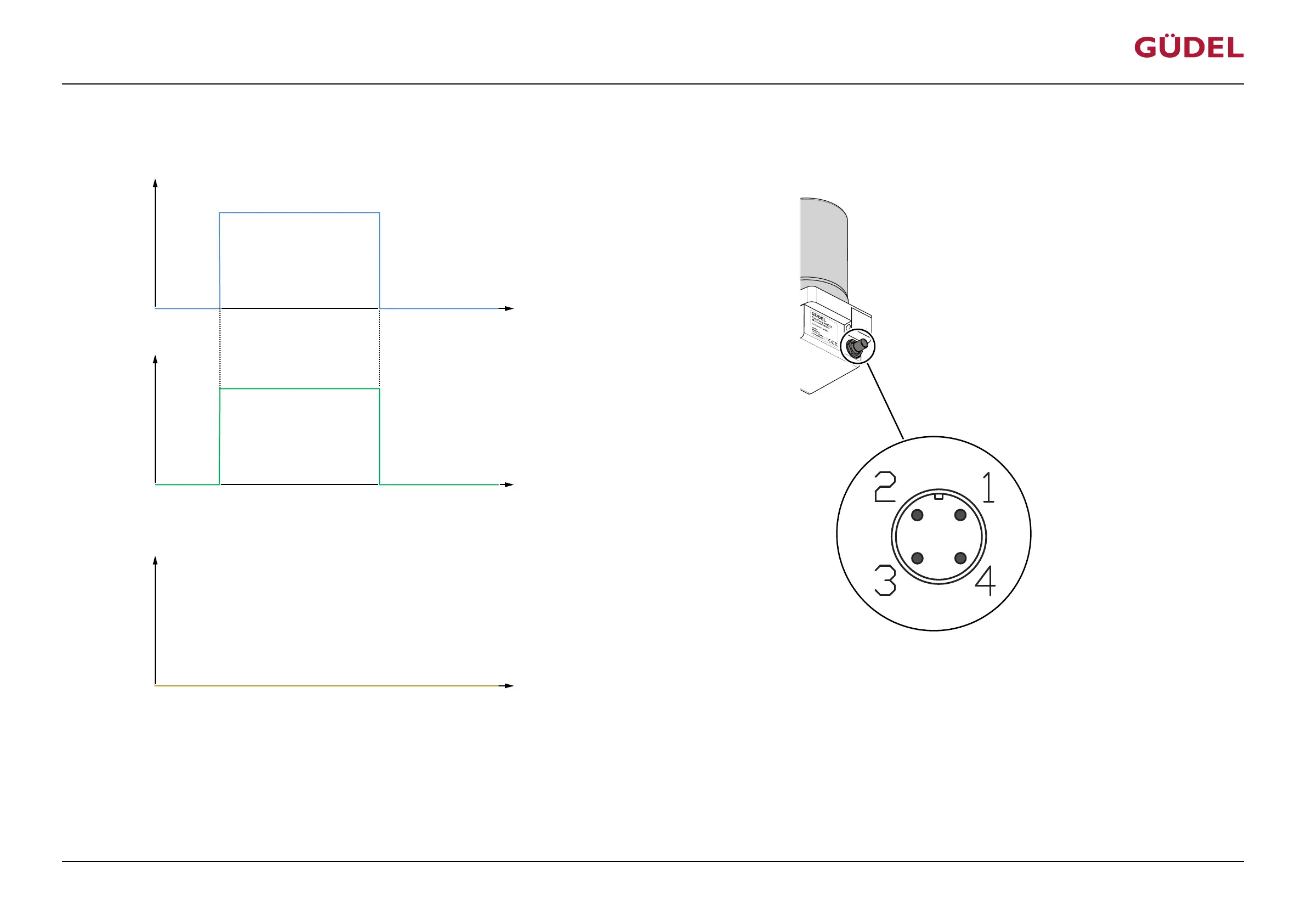
5.6.3.1 Switching on and off
Input signal PIN 1
Output signal PIN 4
U
U
+24 V
(High)
+ 0 V
(Low)
(Low)
+ 0 V
(High)
+24 V
t
t
Hydraulic output
t
V
Fig.5-11 Switching time diagram: Switch on and switch off
The lubrication system is switched on as long as PIN 1 has a continuous supply of +24VDC voltage. Any information saved will not be lost when the lubrication system is switched off. The output sig-
nal at PIN4 in normal operation is High (20…30V). The lubrication system has to be controlled by a PLC for it to dispense lubricant on a regular basis. For this purpose, a pulse rhythm for each con-
trol signal must be sent for every lubrication cycle.
CommissioningOPERATING MANUAL FlexxPump4N Lubrication System
3422906891_v1.0_EN-US
63