13
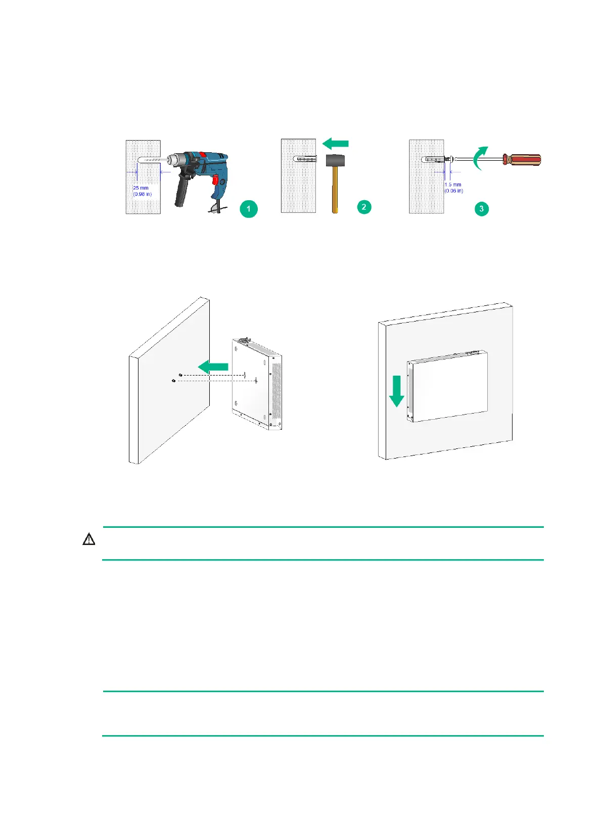
2. Drill two holes with a diameter of 6 mm (0.24 in) (7 mm/0.28 in for an S5130S-16S-PWR-EI
switch) and a depth of 25 mm (0.98 in) at the marked locations. Hammer the screw anchors into
the wall and use a Phillips screwdriver to fasten the screw into the screw anchor. Leave 1.5 mm
(0.06 in) between the screw head and the wall for hanging the switch.
Figure 12 Installing the switch on a wall (2)
3. Align the installation holes in the switch rear with the screws on the wall and hang the switch on
the screws. Make sure the port side faces down and the left and right sides are perpendicular to
the ground.
Figure 13 Installing the switch on a wall (3)
Grounding the switch
!
Correctly connecting the switch grounding cable is crucial to lightning protection and EMI protection.
The power input end of the switch has a noise filter, whose central ground is directly connected to the
chassis to form the chassis ground (commonly known as PGND). You must securely connect this
chassis ground to the earth to minimize the potential for system damage, maximize the safety at the
site, and minimize EMI susceptibility of the system.
You can ground the switch in one of the following ways, depending on the grounding conditions
available at the installation site:
Grounding the switch with a grounding strip
Grounding the switch with a grounding conductor buried in the earth ground
chassis views and power module and grounding terminal positions in the following figures are

 Loading...


