23
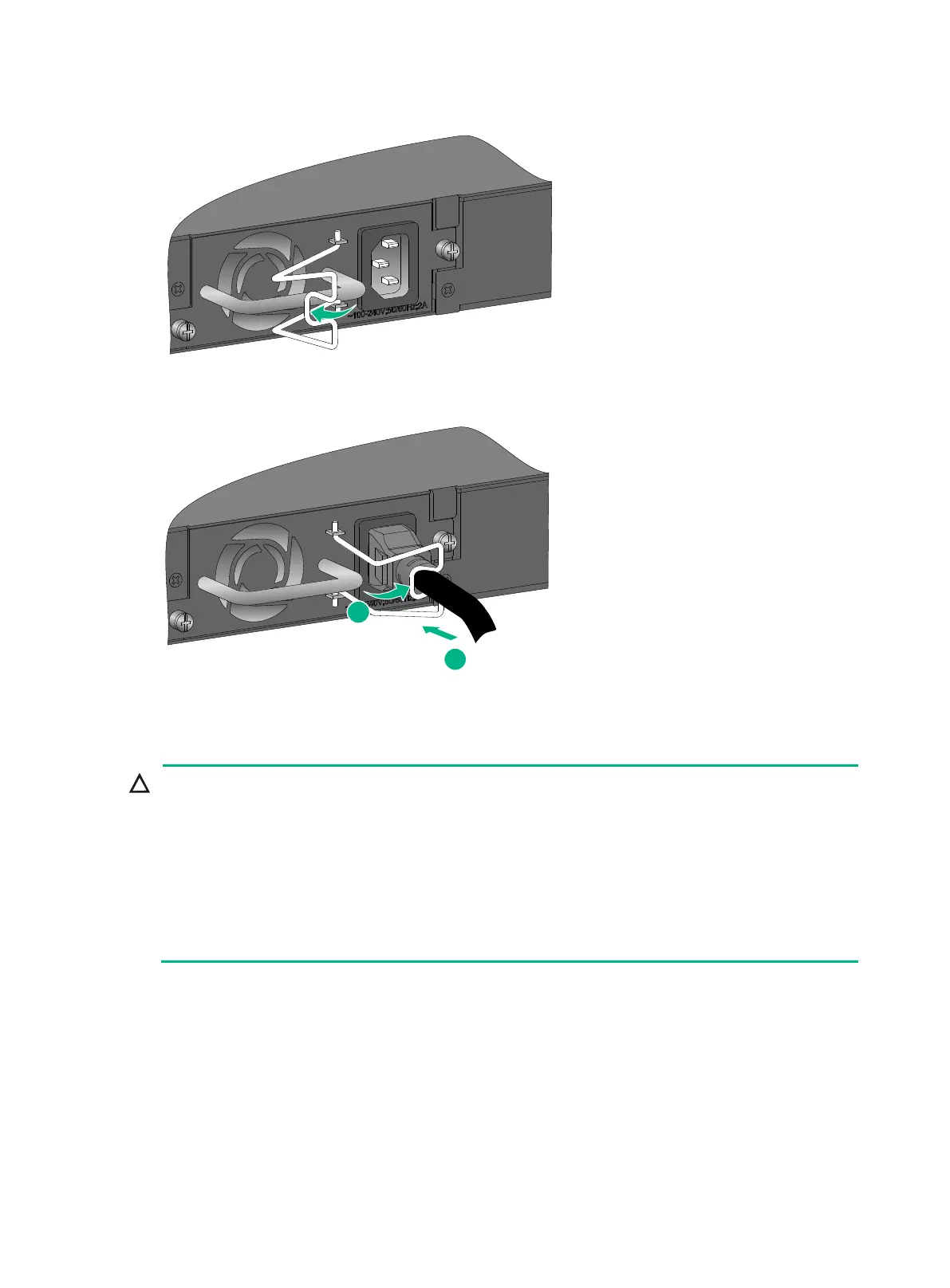
Figure 28 Connecting the power cord for a PSR75-12A/PSR150-A1 power module (1)
Figure 29 Connecting the power cord for a PSR75-12A/PSR150-A1 power module (2)
Connecting the power cord for a PSR150-D1 power module
Connect the other ends of the wires for a PSR150-D1 power module to a –
with the negative wire (– or L–) to the negative terminal (–) and the positive wire (+ or M/N
positive terminal (+).
To use an H3C RPS to supply power to the power module, use a compatible RPS power cord to
connect the RPS to the power module.
The power cord color code scheme in Figure 30 is for illustration only. The cable delivered for
your country or region might use a different color scheme. When you connect the power cord,
always identify the polarity symbol on its wires.
To connect the power cord for a PSR150-D1 power module:
1. Correctly orient the plug at one end of the cable with the power receptacle on the power module,
and insert the plug into the power receptacle. See callout 1 in Figure 30.
If you cannot insert the plug into the receptacle, re-orient the plug rather than use excessive
force to push it in.
2. Tighten the screws on the plug with a flat-blade screwdriver to secure the plug in the power
receptacle. See callout 2 in Figure 30.
3. Connect the other end of the power cord to a –48 VDC power source or an RPS.

 Loading...


