15
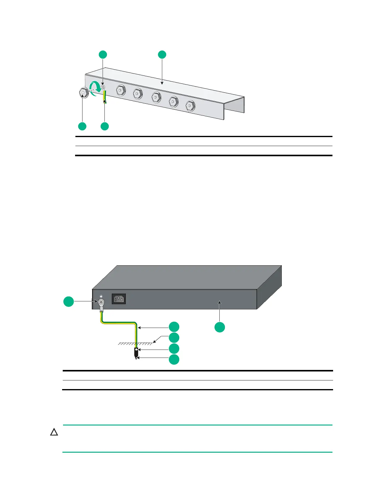
Figure 15 Connecting the grounding cable to a grounding strip
Grounding the switch with a grounding conductor buried in
the earth ground
If the installation site has no grounding strips, but earth ground is available, hammer a 0.5 m (1.64 ft)
or longer angle iron or steel tube into the earth ground to serve as a grounding conductor.
The dimensions of the angle iron must be at least 50 × 50 × 5 mm (1.97 × 1.97 × 0.20 in). The steel
tube must be zinc-coated and its wall thickness must be at least 3.5 mm (0.14 in).
Weld the yellow-green grounding cable to the angel iron or steel tube and treat the joint for corrosion
protection.
Figure 16 Grounding the switch by burying the grounding conductor into the earth ground
Installing and removing power modules
Provide a circuit breaker for each power
module and make sure the circuit breaker is off before

 Loading...


