34
Device model
Candidate IRF physical
ports
Restrictions for using the ports for
IRF connections
Other S5130S-EI switch
models
All the following ports on the
front panel:
• 10/100/1000BASE-T
autosensing ports
• SFP ports
The port must operate at 1 Gbps.
The IRF physical ports on the member
switches must be same type.
For switches with 52 service ports, the service
ports are divided into two groups: ports 1 to
24, port 51, and port 52 in one group and
ports 25 to 50 in the other group.
To bind multiple ports to an IRF port, make
sure the ports are in the same group. Ports in
one group can be bound to different IRF ports.
Planning the cabling scheme
Use the following cables to connect the IRF physical ports on the switches:
Category 5 or above twisted-pair cable—10/100/1000BASE-T autosensing Ethernet ports.
Category 5e or above twisted-pair cable—5G/2.5G/1000BASE-T autosensing Ethernet
ports.
Category 5e or above twisted-pair cable—2.5G/1000/100BASE-T autosensing Ethernet
ports.
Category 6 or above twisted-pair cable—10/5/2.5/1GBASE-T autosensing Ethernet ports.
GE SFP transceiver modules and optical fiber or SFP cable—SFP ports. For the available
models, see "Appendix C Ports and LEDs."
SFP+ transceiver modules and optical fiber or SFP+ cable—SFP+ ports. For the available
models, see "Appendix C Ports and LEDs."
If the IRF member switches are far away from one another, use SFP/SFP+ transceiver modules and
optical fibers. If the IRF member switches are all in one equipment room, use twisted pair cables or
SFP/SFP+ cables.
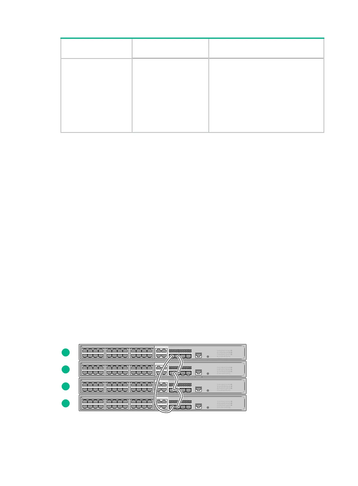
As a best practice, use ring topology to connect the switches. The following describes cabling
schemes in ring topology.
Connecting the IRF member switches in one rack
Use SFP cables to connect the IRF member switches in a rack as shown in Figure 39. The switches
in the ring topology (see Figure 40) are in the same order as connected in the rack.
Figure 39 Connecting the switches in one rack

 Loading...


