105
4&5 Axis Programming
96-8000 rev R June 2007
4TH AND 5TH AXIS PROGRAMMING
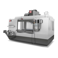
SIDE
A-AXIS
+32°-32°+32° -32°
FRONT
B-AXIS
B-Axis 360º
A-Axis ±120º
Axis motion on the VR-11 Mill and the Haas TRT 210
CREATING F IVE-AXIS P ROGRAMS
Most five-axis programs are rather complex and should be written using a CAD/CAM package. It is necessary to
determine the pivot length and gauge length of the machine, and input them into these programs.
Each machine has a specific pivot length. This is the distance from the spindle head’s center of rotation to the
bottom surface of the master tool holder. The pivot length can be found in Setting 116, and is also engraved into the
master tool holder that is shipped with a 5-axes machine.
Axis of
Rotation
Gauge Length
Pivot Length
Total
When setting up a program, it will be necessary to determine the gauge length for each tool. The gauge length is
the distance from the bottom flange of the master tool holder to the tip of the tool. This distance can be calculated
by setting a magnetic base indicator on the table, indicating the bottom surface of the master tool holder, and
setting this point as Z0 in the control. Then, insert each tool, and calculate the distance from the tool tip to the Z0;
this is the gauge length.
The total length is the distance from the spindle head center of rotation to the tip of the tool. It can be calculated by
adding the gauge length and pivot length. This number is entered into the CAD/CAM program, which will use the
value for its calculations.
Offsets
The work-offset display is found on the offset display by pushing the Page Up button. You can display and manually
enter work offsets from here. The G54 through G59 or G110 through G129 offsets can be set by using the Part Zero
Set button. Position the axes to the work zero point of your part. Using the cursor, select the proper axis and work
number. Press the Part Zero Set button and the current machine position will be automatically stored in that
address. This will work with only the work zero offsets display selected. Note that entering a nonzero Z work offset
will interfere with the operation of an automatically entered tool length offset.