115
G Codes
96-8000 rev R June 2007
A chamfer block or a corner-rounding block can be automatically inserted between two linear interpolation blocks
by specifying ,C (chamfering) or ,R (corner rounding). There must be a terminating linear interpolation block follow-
ing the beginning block (a G04 pause may intervene). These two linear interpolation blocks specify a corner of
intersection. If the beginning block specifies a C, the value following the C is the distance from the intersection to
where the chamfer begins, and also the distance from the intersection to where the chamfer ends. If the beginning
block specifies an R, the value following the R is the radius of a circle tangent to the corner at two points: the
beginning of the corner-rounding arc and the endpoint of that arc. There can be consecutive blocks with chamfering
or corner rounding specified. There must be movement on the two axes specified by the selected plane, whether
the active plane is XY (G17), XZ (G18) or YZ (G19).
G02 CW / G03 CCW Circular Interpolation Motion (Group 01)
F Feedrate in inches (mm) per minute
I Optional distance along X axis to center of circle
J Optional distance along Y axis to center of circle
K Optional distance along Z axis to center of circle
R Optional radius of circle
X Optional X-axis motion command
Y Optional Y-axis motion command
Z Optional Z-axis motion command
A Optional A-axis motion command
,R Radius of corner rounding circle
,C Distance from the center of intersection where chamfer begins.
These G codes are used to specify circular motion. Two axes are necessary to complete circular motion and the
correct plane, G17-19, must be used. There are two methods of commanding a G02 or G03, the first is using the I,
J, K addresses and the second is using the R address.
A chamfer or corner-rounding feature can be added to the program, by specifying ,C (chamfering) or ,R (corner
rounding), as described in the G01 definition.
Using I, J, K addresses
I, J and K address are used to locate the arc center in relation to the start point. In other words, the I, J, K ad-
dresses are the distances from the starting point to the center of the circle. Only the I, J or K specific to the
selected plane are allowed (G17 uses IJ, G18 uses IK and G19 uses JK). The X, Y, and Z commands specify the
end point of the arc. If the X, Y, or Z location for the selected plane is not specified, the endpoint of the arc is the
same as the starting point for that axis.
To cut a full circle the I, J, K addresses must be used; using an R address will not work. To cut a full circle, do not
specify an ending point (X, Y and Z); program I, J or K to define the center of the circle. For example: G02 I3.0 J4.0
(Assumes G17; XY plane)
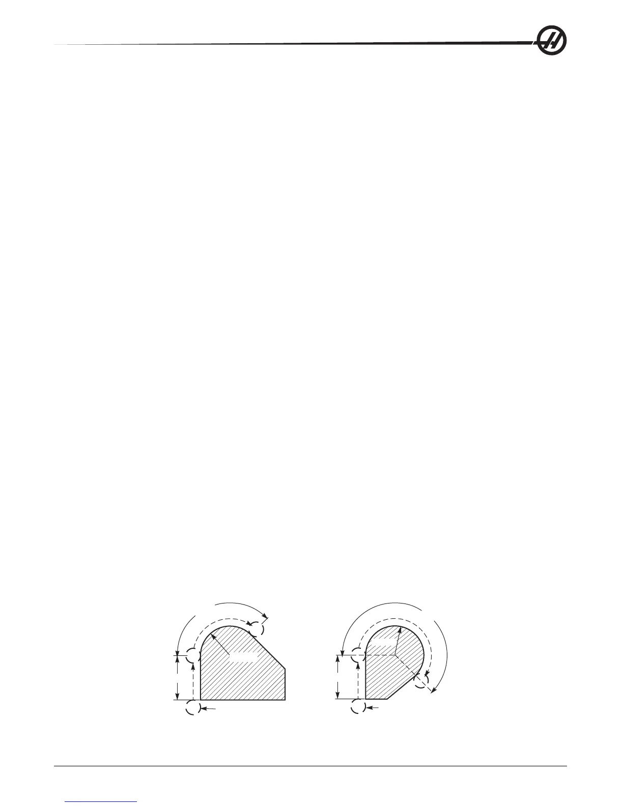
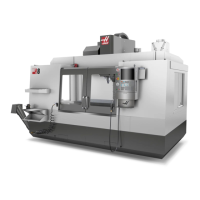
Using the R address
The R-value defines the distance from the starting point to the center of the circle. Use a positive R-value for radii of
180° or less, and a negative R-value for radii more than 180°.
Programming Examples
1.5
135
O
R 1.00
.5Ø
225
O
.5Ø
1.5
R 1.00
G90 G54 G00 X-0.25 Y-.25
G01 Y1.5 F12.
G02 X1.884 Y2.384 R1.25
G90 G54 G00 X-0.25 Y-0.25
G01 Y1.5 F12.
G02 X1.884 Y0.616 R-1.25