Operation
38
96-8000 rev R June 2007
Floppy Disk DNC
Floppy disk DNC is selected by entering the floppy disk file name and pressing MDI a second time when (must be
in MDI mode). Note: Pressing MDI a third time will stop the DNC and the message “DISK ABORT” will be received.
DNC Notes:
While a program is running in DNC, you cannot change modes. Therefore, editing features such as Background
Edit is not available.
DNC supports Drip Mode. The control will perform one block (command) at a time. Each block will be performed
immediately with no block look-ahead. The exception is when Cutter Compensation is commanded. Cutter Com-
pensation requires three blocks of motion commands to be read prior to a compensated block being performed.
Full duplex communication during DNC is possible by using the G102 command or DPRNT to output axes coordi-
nates back to the controlling computer.
ALPHABETICAL A DDRESS C ODES
The following is a list of the address codes used in programming the CNC.
Axis motion – Specifies
axis motion (distance or angle).
Tool diameter selection – Selects the tool
diameter or radius used for cutter compensation.
See the Cutter Compensation section.
Contouring accuracy – Used, with G187, to select
the accuracy required when cutting a corner during
high-speed machining operations.
Feed rate – Used to enter a feed rate; the value is
entered in inches per minute or mm per minute.
Preparatory functions – See the chapters on
G or M codes.
Tool length offset selection – Selects the tool
length offset. The H is followed by a number
between 0 and 200.
Canned cycle and circular optional data –
These address characters are used to specify data
for some canned cycles and circular motions. They
are entered either as inches or mm.
Loop count for repeated cycles – Specifies a
repetition count for some canned cycles and
auxiliary functions.
A, B, C, U, V, W, X, Y, Z
D
E
F
G, M
H
I, J, K
L
N
O
P
Q
R
S
T
Number of block – Identifies or numbers each
block of a program (optional).
Program number/name – Used to identify a
program. It is followed by a number between 0 and
99999.
Delay time or program number – Used to enter
either a time in seconds or a program number for a
subroutine call.
Canned cycle optional data – Used in canned
cycles and is followed by a signed number, between
0 and 8380.000 for inches or between 0 and
83800.00 for metric.
Canned cycle and circular optional data –
Defines the reference plane for canned cycles and
circular interpolation. R is followed by a signed
number between -15400.0000 and 15400.0000 for
inches or between -39300.000 and 39300.000 for
millimeters.
Spindle speed command – Used to specify the
spindle speed.
Tool selection code – Used to select the tool for
the next tool change.
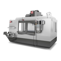
PART S ETUP
It is necessary to properly secure the part to the table. This can be done a number of ways, using vises, chucks or
using T-bolts and toe clamps.
Toe Clamp
Chuck
Vise