69
Subroutines
96-8000 rev R June 2007
SUBROUTINE C ANNED C YCLE E XAMPLE
Sub Program
O1234 (Canned Cycle Example Program) O1000 (X,Y Locations)
T1 M06 X 1.115 Y-2.750
G90 G54 G00 X.565 Y-1.875 S1275 M03 X 3.365 Y-2.875
G43 H01 Z.1 M08 X 4.188 Y-3.313
G82 Z-.175 P.03 R.1 F10. X 5.0 Y-4.0
M98 P1000 M99
G80 G00 Z1.0 M09
T2 M06
G00 G90 G54 X.565 Y-1.875 S2500 M03
G43 H02 Z.1 M08
G83 Z-.720 Q.175 R.1 F15.
M98 P1000
G00 G80 Z1.0 M09
T3 M06
G00 G90 G54 X.565 Y-1.875 S900 M03
G43 H03 Z.2 M08
G84 Z-.600 R.2 F56.25
M98 P1000
G80 G00 Z1.0 M09
G28 G91 Y0 Z0
M30
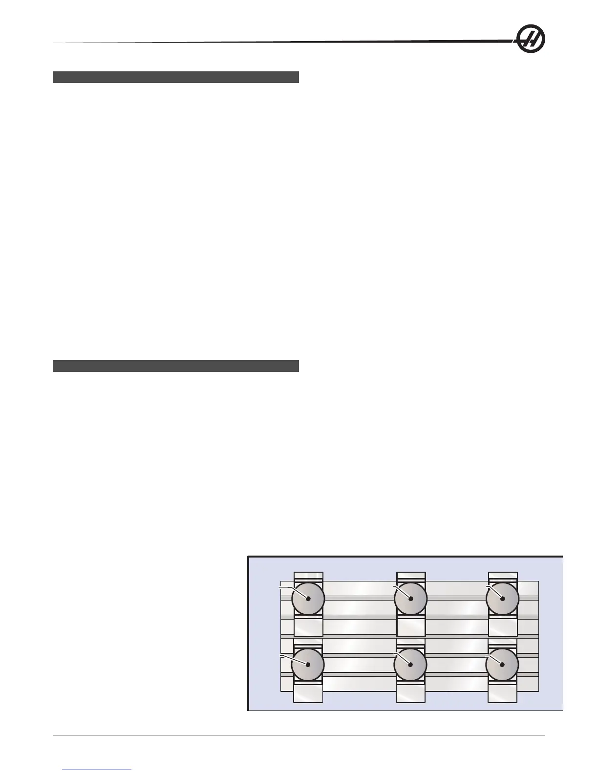
SUBROUTINES W ITH M ULTIPLE F IXTURES
Subroutines can also be useful when cutting the same part in different X and Y locations within the machine. For
example, there are six vises mounted on the table. Each of these vises will use a new X, Y zero. They will be
referenced in the program using the G54 through G59 work offsets. Use an edge finder or an indicator to establish
the zero point on each part. Use the part zero set key in the work coordinate offset page to record each X, Y
location. Once the X, Y zero position for each workpiece is in the offset page, the programming can begin.
The figure shows what this setup would look like on the machine table. For an example, each of these six parts will
need to be drilled at the center, X and Y zero.
Main Program Subroutine
O2000 O3000
T1 M06 X0 Y0
G00 G90 G54 X0 Y0 S1500 M03 G83 Z-1.0 Q.2 R.1 F15.
G43 H01 Z.1 M08 G00 G80 Z.2
M98 P3000 M99
G55
M98 P3000
G56
M98 P3000
G57
M98 P3000
G58
M98 P3000
G59
M98 P3000
G00 Z1.0 M09
G28 G91 Y0 Z0
M30
X0, Y0
X0, Y0
X0, Y0
X0, Y0
X0, Y0
X0, Y0
G54 G55 G56
G57 G58
G59