82
96-8000 rev R June 2007
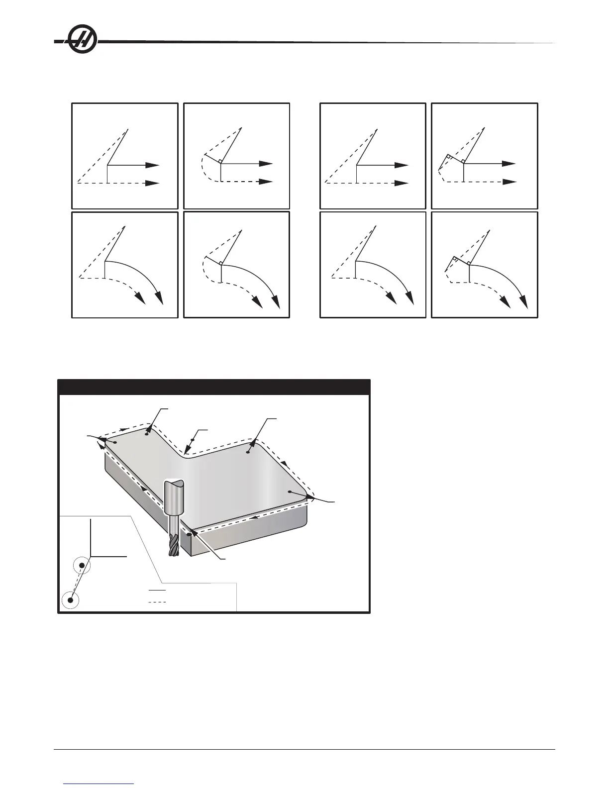
Cutter Compensation
Program Path
Tool Center Path
Program Path
Tool Center Path
Program Path
Tool Center Path
Type A Type B
Program Path
Program Path
Tool Center Path
Program Path
Tool Center Path
Type A Type B
Program Path
Program Path
Tool Center Path
Cutter Compensation Entry (YASNAC) Cutter Compensation Entry (Fanuc style)
Tool Center Path
Tool Center Path
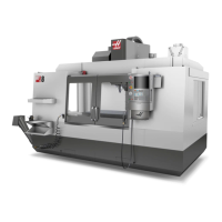
The following illustration shows how the tool path is calculated for the cutter compensation. The detail section
shows the tool in the staring position and then in the offset position as the cutter reaches the workpiece.
X0, Y0
X1., Y1.
Start Position
Offset Tool Path
R .375
R .5625
X0, Y0
R .3437
R .375
R .500
G02 & G03
Circular Interpolation
G02 & G03
Circular Interpolation
Note: Tool is a .250” diameter
end mill.
Note: Tool is a .250” diameter
end
mill.
Programmed Path
Center of Tool
%
O6100
T1 M06
G00 G90 G54 X-1. Y-1. S5000 M03
G43 H01 Z.1 M08
G01 Z-1.0 F50.
G41 G01 X0 Y0 D1. F50.
Y4.125
G02 X.250 Y4.375 R.375
G01 X1.6562
G02 X2.0 Y4.0313 R.3437
G01 Y3.125
G03 X2.375 Y2.750 R.375
G01 X3.5
G02 X4.0 Y2.25 R.5
G01 Y.4375
G02 X3.4375 Y-.125 R.5625
G01 X-.125
G40 X-1. Y-1.
G00 Z1.0 M09
G28 G91 Y0 Z0
M30
Programming exercise showing tool path.
The following program uses cutter compensation. Tool path is programmed to centerline of the cutter. This is also
the way the control calculates for cutter compensation.