Page 114
Pump Tube Replacement
UVTOCMaintenance.fm
Section 7
tubing retainer grooves up. Shift the pump head slightly until it snaps on
the alignment pins (if present).
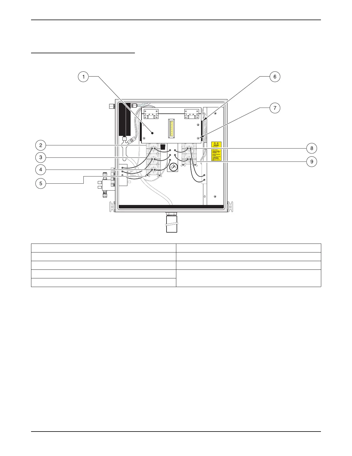
Figure 35 Pump Module Assembly
10. Connect any reduction tubing using barb reducers as dictated by the
pump kit.
11. Secure with the four screws provided. Finger tighten only.
12. Slide the first pump head onto the mounting screws.
13. Place the key in the slot on the rotor shaft. Twist the shaft to align the tang
on the rotor shaft with the slot in the motor drive shaft. Shift the pump
head housing around until it drops over the alignment pins, if present
(Figure 38 on page 116).
14. Repeat the installation steps for each additional pump head, aligning the
pump head tang with the slot on the previously mounted pump head.
15. Secure the four wing nuts. Finger tighten only.
1. Pump Module Assembly 6. Pump Module Prop (One on each side of pump module)
2. Acid Pump Head 7. Captive Screw (4)
3. Sample Pump Head 8. Persulfate Pump Head
4. Dilution Pump 9. Resample Pump Head
5. Wing Nut (four per pump head)