Page 46
Carrier Gas and Fluid Connections
UVTOCUnpacking Installation Setup.fm
Section 2
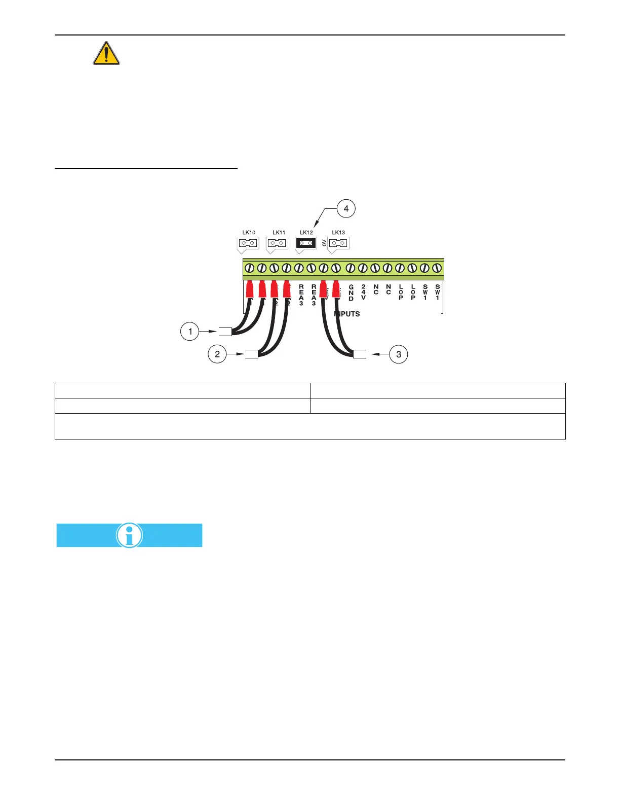
2.5.3 Optional Level Detector Configuration
Optional level detectors may be installed to warn of low reagent levels or a
high wastewater level in the drain pan. Figure 26 shows connections and
jumper configurations that are made on the I/O PCB. A signal from a sensor
indicates a low reagent level.
If a third reagent level detector is used, remove the jumper from LK12 and
install the sensor on terminals 11 and 12.
Figure 26 Optional Level Detector Connections and Setup
2.6 Carrier Gas and Fluid Connections
2.7 Connection Information
Accommodate samples between
70–100 °C (160–212 °F) using
an external cooler consisting of
a 3000 mm (120-in.) long, 6 mm
(¼-in.) O.D. stainless steel
sample inlet tube at a flow rate
of 25–60 mL/minute.
Carrier gas and fluid connections are made on the lower left-hand side of the
analyzer. Refer to Figure 27 on page 48. After connections are made, ensure
that they are leak free.
On non-dilution analyzers a connection to the dilution port is not necessary.
Plug the dilution port.
If the analyzer is not equipped with a fast-loop sweep, the sample port may be
connected to an ambient pressure source.
If the analyzer is equipped with a fast-loop sweep, the sample entry port can
be connected to a pressurized source of up to 6 bar (87 psi), with a control
valve (needle valve) placed on the inlet to throttle down the flow to between
25 and 200 mL/min.
1. Reagent Level Detector 1 connected to REA 1 3. Internal Level Detector
2. Reagent Level Detector 2 connected to REA 2 4. LK12
Important Note: A jumper is installed on LK12 when the Optional Level Detectors are connected. If a Reagent Level Detector
is removed, a jumper must be placed on the corresponding link, (LK10 = REA 1, LK11 = REA 2).