Page 42
Serial Data Connections
UVTOCUnpacking Installation Setup.fm
Section 2
2.5.1 Installation
Important Note: The analyzer circuit board components are sensitive to static
electricity damage. Do not touch circuit boards or their components without wearing a
properly grounded wrist strap. See Electrostatic Discharge (ESD) Considerations on
page 111.
Danger: Remove power to the
analyzer if any electrical work is
to be performed. See Safety Note
10 on page 185 for Spanish,
French, German, or Italian
translations.
1. Remove ac power to the analyzer and the 8001 Termination Assembly.
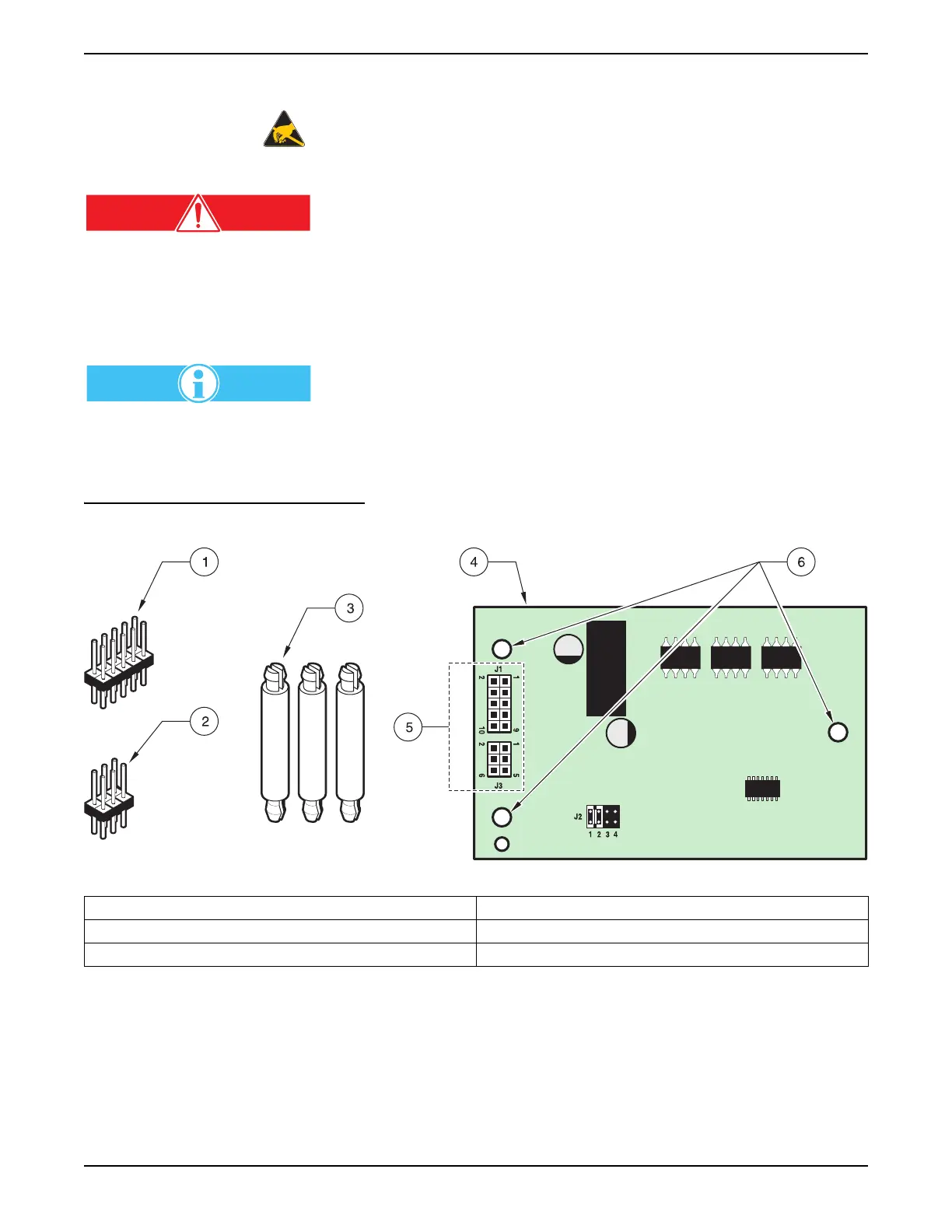
2. Press the three supplied plastic standoffs into the communications
interface circuit board, see Figure 20.
3. Insert the short side of the double-ended header pins into the
communications interface circuit board header plugs.
4. Locate the two electronic header plugs on the 8001Termination Assembly,
and insert the opposite end of the header pins into the I/O assembly.
The Communications Interface Kit
may contain different height
standoffs and headers. Use only the
items detailed in Figure 20.
5. Press the plastic standoffs into the I/O Assembly to support the
circuit board.
6. Jumper configuration for J2 is detailed in the kit.
Figure 20 Communication Kit Components
1. J1 Header (10-pin, 18.5 mm (0.63in.) 4. RS232 or RS485 PCB (components will be facing down)
2. J3 Header (6-pin, 18.5 mm (0.63 in.) 5. J1 and J3
3. Standoffs (25.4 mm (1 in) 6. Mounting Holes for Stand-offs