Section 4
Page 59
UVTOCCommissioning.fm Analyzer Adjustments
8. Place the sample stream line back into DI water.
9. Allow the reading to stabilize to lower than 30 ppm CO
2
.
10. Enter the Calibration/Primary Zero menu and follow the
prompted procedure.
11. Visually ensure that the CO
2
ppm is stable. Because the analyzer has
already analyzed DI water, press ENTER repeatedly to skip the elapsing
time and advance to the final screen.
12. Go back to the Main screen.
13. Connect the sample stream line to the sample source.
14. Set-up the local parameter settings such as Auto-cal, Auto-clean, Relays,
Analog outs, etc. as described in the instrument manual.
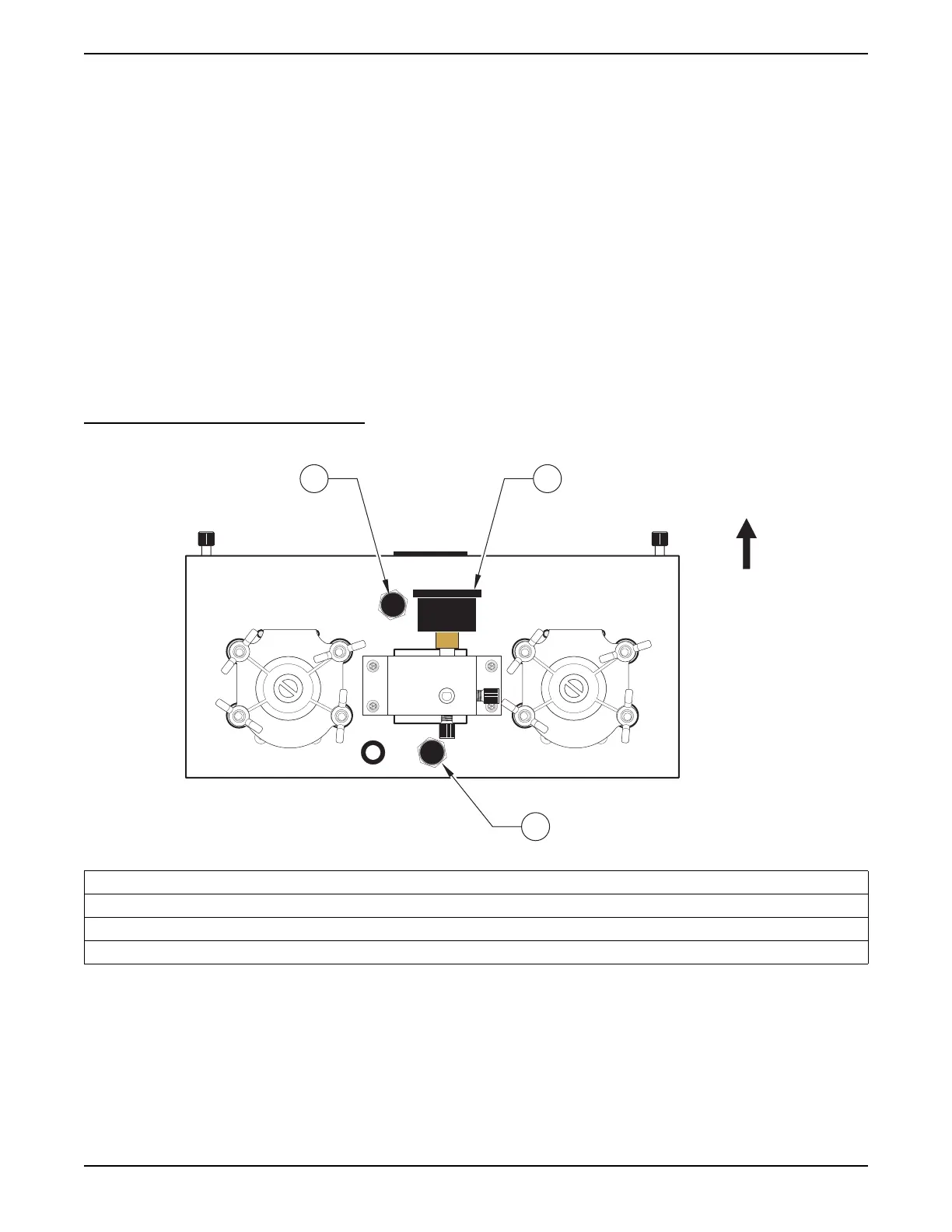
Figure 29 Bottom View of the Pump Bracket Assembly
1. Flow Adjustment Knob
2. Pressure Gauge
3. Pressure Regulator Knob (Turn clockwise to decrease pressure. Turn counter-clockwise to increase pressure.)
Note: To access the pressure regulator, carefully open the pump module without pulling any tubing off of the barb fitting.
12
3
Front of
analyzer.