14 of 82 Initialization - 9705
KSS - March 2006 - Edition 1
Operator Manual HIAC
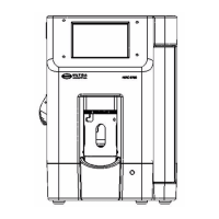
2.2 9705 Components
Figure 2-2 shows the locations of connectors on the back panel of the 9705.
Place the particle counter on a dry, level surface. Do not power up any instruments until all
electrical and communications connections are complete.
2.3 Fluid Connections
2.3.1 Connecting the Drain Line
1) Attach the drain line to the back of the unit.
2) Be sure the connection is secure before powering on the unit.
3) Place the other end of the drain line in a suitable waste-fluid receptacle.
o
e:
The sensor cleaning port is located on the left side of the unit below the printer. For more
information, refer to “Sensor Port Cleaning” on page 62.
Fig 2-2 : Rear View of 9705
drain USB service power
 Loading...