4-36 888-2463-001 3/6/08
WARNING: Disconnect primary power prior to servicing.
Diamond Series™
Section 4 Theory of Operation
In our applications, PIN diodes in parallel with 50 ohm resistors are used instead of
rheostats. The amount of bias current through the diodes controls their RF impedance.
The impedances seen at ports 2 and 3 are the parallel combination of the 50 ohm and
PIN diode impedances. When the PIN diodes are biased “off”, they appear as open
circuits, resulting in 50 ohm loads seen at ports 2 and 3. Thus, all of the RF power is
absorbed in the 50 ohm resistors, giving maximum attenuation. If the diodes are biased
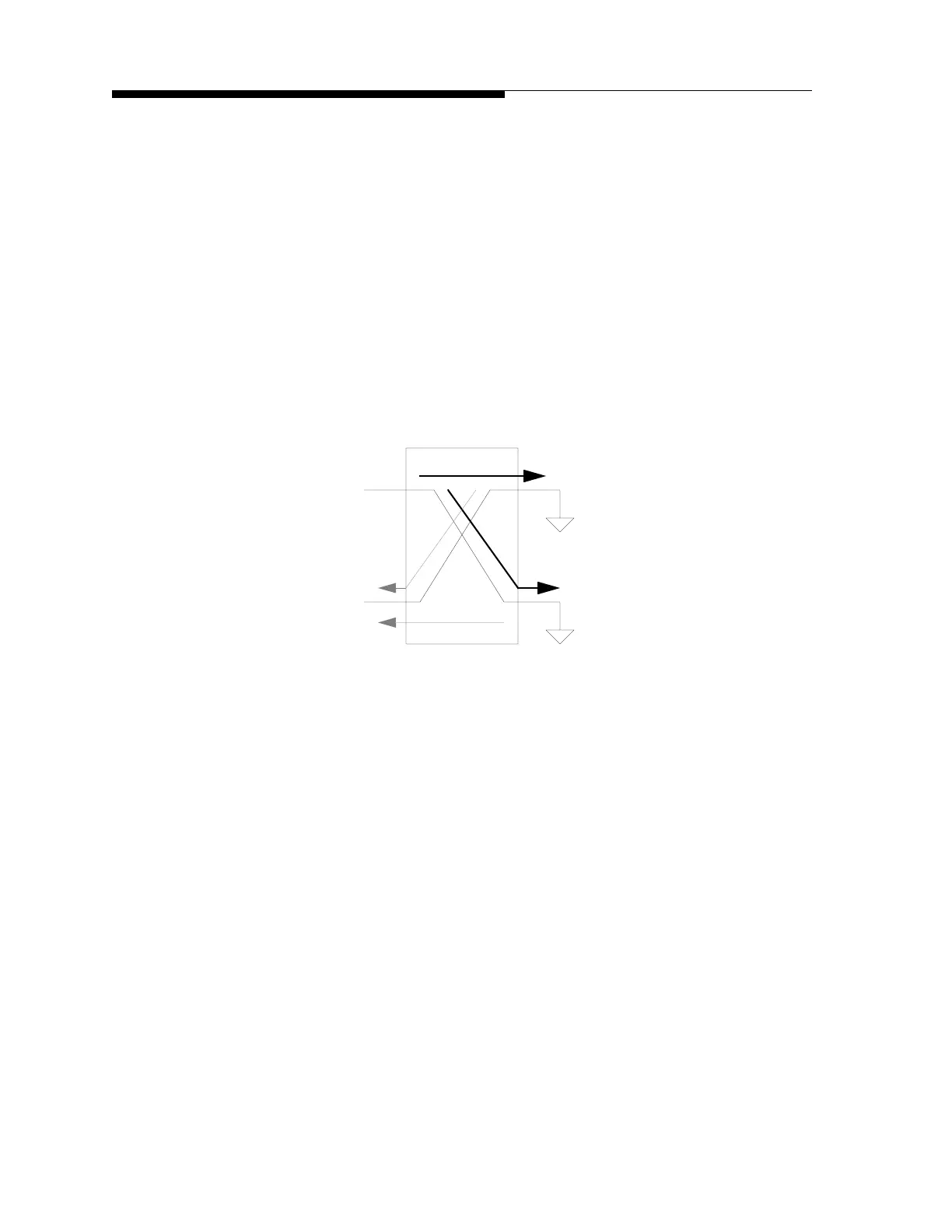
“on,” they appear as short circuits, resulting in short circuits appearing at ports 2 and 3.
This causes complete reflection of the RF power incident on ports 2 and 3, and the RF
recombines at port 4, resulting in minimum attenuation (see Figure 4-3). Varying the
bias current in the PIN diodes varies their impedance and, hence, the amount of
attenuation.
Figure 4-3 No Attenuation
Input
Output
1
2
34
 Loading...

