Iss. a – Translation of the original version
Doc. Ref. : SOUND2.940.001
List of figures
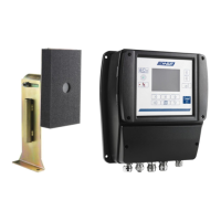
Figure 1: Composition of the SOUND2 system ................................................................................................ 13
Figure 2: Presentation of the screen on the unit ............................................................................................. 14
Figure 3: Main page.......................................................................................................................................... 14
Figure 4: Circuit board ...................................................................................................................................... 16
Figure 5: Characteristics of the digital outputs ................................................................................................ 17
Figure 6: Characteristics of the analogue outputs ........................................................................................... 17
Figure 7: CE identification plate ....................................................................................................................... 19
Figure 8: Block diagram of the installation....................................................................................................... 24
Figure 9: Overall dimensions and mounting system for the unit ..................................................................... 25
Figure 10: Location of the microphone ............................................................................................................ 26
Figure 11: Overall dimensions of the microphone ........................................................................................... 26
Figure 12: Composition of the power cable connector .................................................................................... 27
Figure 13: Connecting the power cable ........................................................................................................... 28
Figure 14: DELTRON 592-0301 connector ........................................................................................................ 28
Figure 15: Microphone cable (two wires with shield) - Connector assembly .................................................. 28
Figure 16: Microphone cable (two wires with shield) - Inserting the cable ..................................................... 29
Figure 17: Microphone cable (two wires with shield) - Soldering the wires .................................................... 29
Figure 18: Microphone cable (two wires with shield) - Fitting the shield wire ................................................ 29
Figure 19: Microphone cable (two wires with shield) - Tightening the screw ................................................. 29
Figure 20: Microphone cable (two wires with shield) - Connecting to the microphone ................................. 29
Figure 21: Connection on the PCB end (two wires with shielding) - Wiring diagram ...................................... 30
Figure 22: Microphone cable (two wires with shielding) - Connecting the 2 data bus wires .......................... 31
Figure 23: Microphone cable (two wires with shielding) - Earthing on the cable gland .................................. 31
Figure 24: “Parameters” menu ........................................................................................................................ 32
Figure 25: Checking calibration ........................................................................................................................ 32
Figure 26: “Calibration” menu ......................................................................................................................... 33
Figure 27: “Calibration in progress” menu ....................................................................................................... 34
Figure 28: Saving the configuration ................................................................................................................. 36
Figure 29: Operator menu structure ................................................................................................................ 38
Figure 30: “System\General” menu ................................................................................................................. 39
Figure 31: “System\Security level” menu ........................................................................................................ 39
Figure 32: Changing profile .............................................................................................................................. 40
Figure 33: “System\Software versions” menu ................................................................................................. 40
Figure 34: “Alarm history” menu ..................................................................................................................... 41
Figure 35: “Measures” menu ........................................................................................................................... 41
Figure 36: “Calibration Datas” submenu .......................................................................................................... 42
Figure 37: “Actual Measures” submenu .......................................................................................................... 42
Figure 38: “Actual Measures” submenu .......................................................................................................... 43
Figure 39: Importing the configuration ............................................................................................................ 48
Figure 40: Removing the microphone .............................................................................................................. 48
Figure 41: Removing the microphone mounting bracket ................................................................................ 49
Figure 42: Structure of the Premium maintenance menu ............................................................................... 51
Figure 43: Structure of the Advanced maintenance menu .............................................................................. 52
Figure 44: “Communication Host” submenu ................................................................................................... 54
Figure 45: Example with two mills in the same room ...................................................................................... 55
Figure 46: “Cross Talk” menu ........................................................................................................................... 55
Figure 47: “Analog outputs” menu .................................................................................................................. 56
Figure 48: “Digital outputs” menu ................................................................................................................... 57
Figure 49: “System\General” menu ................................................................................................................. 58
Figure 50: Definition of the parameters on the main screen ........................................................................... 59
Figure 51: “System\Parameters” menu ........................................................................................................... 59
Figure 52: “System\Security” menu ................................................................................................................. 60
Figure 53: Changing the “Maintenance” password ......................................................................................... 60
Figure 54: “System\Communication” menu .................................................................................................... 61
Figure 55: List of spare parts ............................................................................................................................ 63
 Loading...