Electrical connection
22 A0293_06_E00_03 HBM: public MP85A
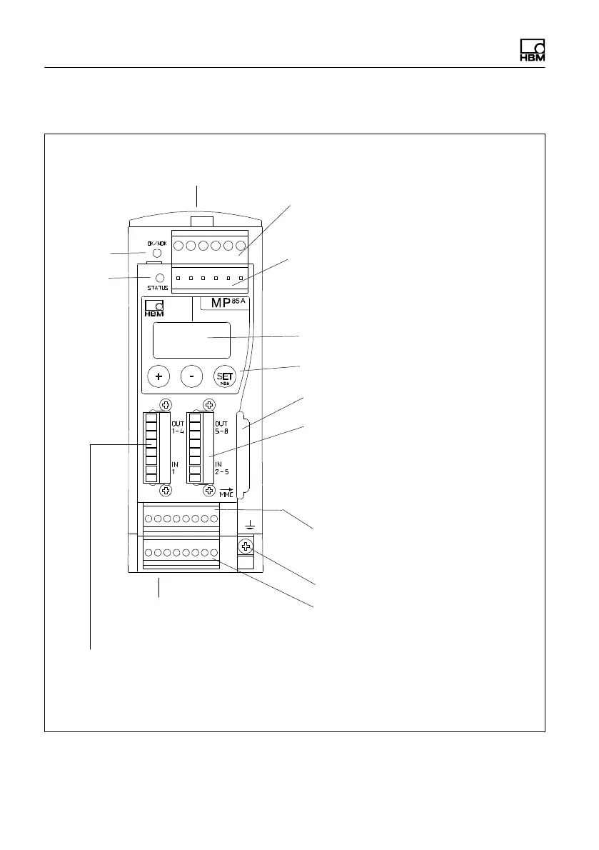
5.2 Overview of MP85A(-S) functions
Screw terminal 1:
Power supply and CAN bus, synchronization
Screw terminal 5:
Transducer connection channel x
including transducer excitation
Control keys
2-line LCD
Screw terminal 2: (same assignment as
screw terminal 1)
CAN adapter for PC/laptop connection,
parameterization via CAN bus
Screw terminal 6:
Transducer connection channel y
including transducer excitation
LED 1
Local connection of CAN bus, supply
voltage and synchronization between
devices
Screw terminal 4:
4 electrically isolated control inputs or
switch test inputs (24 V level, relative to
input ground screw terminal 3)
4 electrically isolated control outputs (24 V
level, power supply via screw terminal 3)
Screw terminal 3:
1 electrically isolated control input or switch test input (24 V level) incl. input ground,
4 electrically isolated control outputs (24 V level), excitation of external supply for control
outputs or rotary/SSI encoder
Cable shield connection for transducers
Module for MultiMedia card
(MMC)/SD card
LED 2
Connection 7:
RJ45 socket for Ethernet
connection (see page 63)