Installing/removing the MP85A (schematic diagrams)
18 A0293_06_E00_03 HBM: public MP85A
4 Installing/removing the MP85A (schematic
diagrams)
The device must be mounted on a support rail to DIN EN60715, which is
connected to a grounded conductor. Both the support rail and the device must
be free of paint, varnish and dirt at the mounting location.
Important
Automation equipment and devices must be designed so as to ensure
adequate protection or locking against unintentional actuation (e.g. access
control, password protection, etc.).
Protect the device from direct contact with water. The IP rating is IP20.
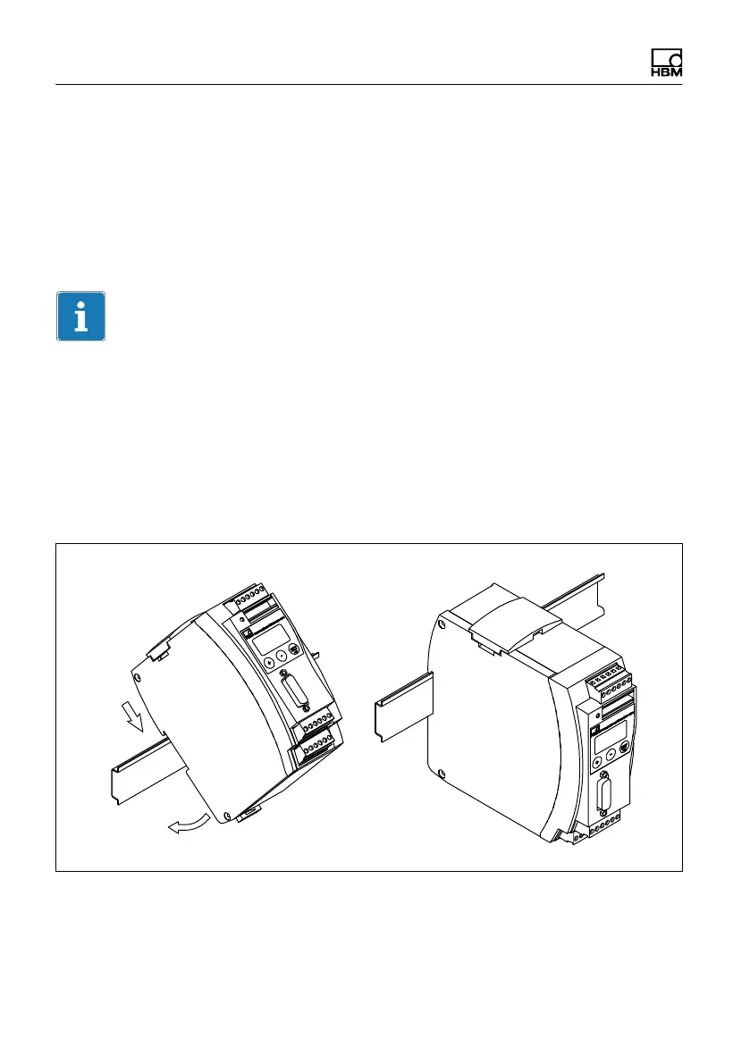
4.1 Mechanical installation/removal
Fig. 4.1 Installation on a support rail