Measurement procedure
MP85A A0293_06_E00_03 HBM: public 75
8.3 Limit monitoring in real time
You can assign and monitor a total of eight limit values in real time for chan
nels x and y. A switching signal of your choice can be assigned to each limit
value. For example, you can switch a press from “fast” to “slow”. The circuit
logic can also be inverted.
8.4 Hiding external tolerances
To hide external tolerances, as caused by different positioning heights of
workpiece holders, for example, you have a choice of various options:
1. Relative x-coordinates
2. Relative y-coordinates
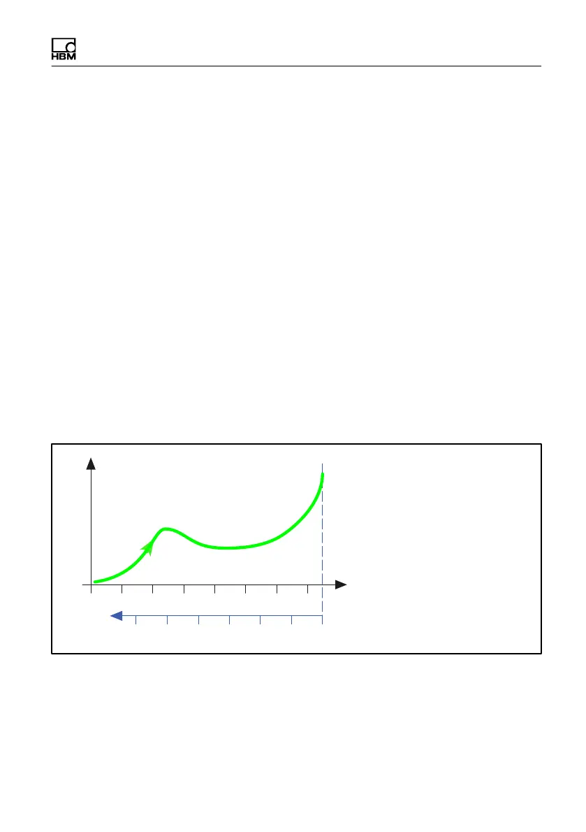
In the first case, you can also select whether analysis should be based on an
end position (Fig. 8.6) or on the y-channel (Fig. 8.7), e.g. if the pin being press-
fitted is touched (force build-up). Displacement is set to zero at this time, and a
second relative axis is plotted to which the coordinates of the evaluation ele
ments now refer.
Measured curve
10 20 30 40 50 60 70
Absolute coordinates
Relative coordinates, end value 00-10-20-30-40-50-60
End position
Fig. 8.6 Reference values for relative x-coordinates, based on end position