Electrical connection
24 A0293_06_E00_03 HBM: public MP85A
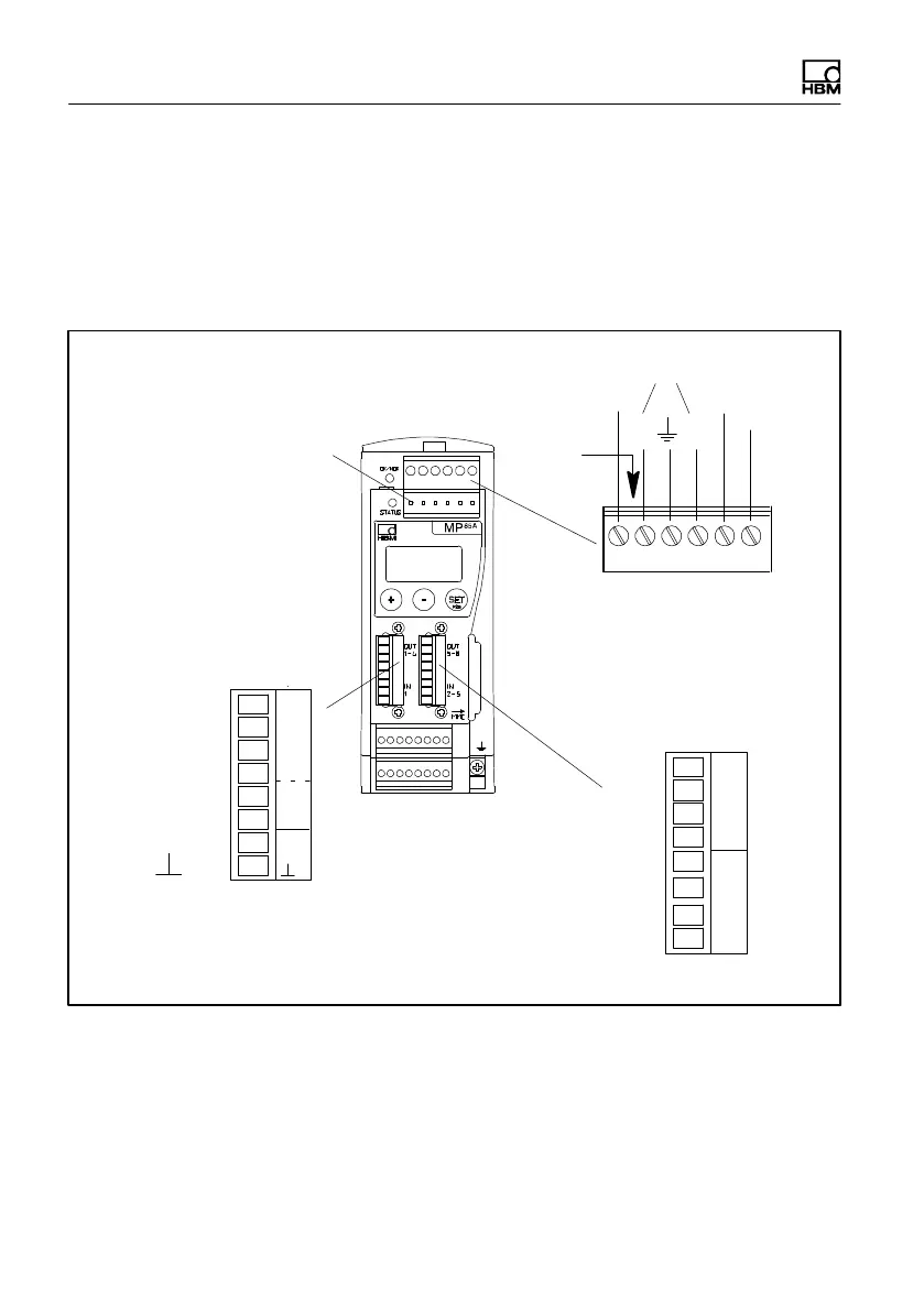
5.4 Supply voltage and control inputs/outputs
Four (MP85A(‐S)) or three (MP85ADP(-S)/MP85ADP-PN(‐S)) plug-in screw
terminals are available for connecting the power supply and control inputs and
outputs. You can assign the functions of the control inputs and outputs as you
wish using the PME Assistant (“Digital inputs/outputs” menu).
0 V
SYNC
Screw terminal 3
(control inputs/outputs,
switch test inputs)
LH
Screw terminal 1
(CAN bus power supply,
synchronization)
IN = digital input OUT = digital output
Important: If the supply voltage to the MP85A process
controller fails, all control outputs are set to 0 V.
24 V
Labeling
CAN
Screw terminal 2
(CAN adapter; assignment
as screw terminal 1)
Screw terminal 4
(MP85A(-S) only)
(control inputs/outputs,
switch test inputs)
Out 1
Out 2
Out 3
Out 4
0 V
24 V
IN 1
Out 5
Out 6
Out 7
Out 8
IN 2
IN 3
IN 4
IN 5
IN
1
2
OUT
3
4
0V
24V
IN
1
5
6
OUT
7
8
2
3
IN
5
4
Fig. 5.1 Screw terminal assignment
The screw terminals are coded to stop them being inserted in the wrong
socket. The sockets have coding tabs, screw terminals 1 and 2 have coding
pins. The coding lugs are broken off for screw terminals 3 and 4.