Electrical connection
MP85A A0293_06_E00_03 HBM: public 33
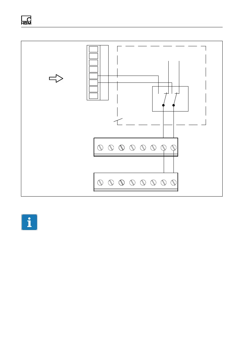
Screw terminal 3
Screw terminal 5
Screw terminal 6
78
5
6
S1
GND +5 V (int)/24 V (ext.)
GND_int 5 V_int
GND_ext
24 V_ext
78
Internal MP85A
wiring
External
power supply
Fig. 5.8 Power supply of active sensors (schematic diagram)
Important
The amplitudes of the measurement signal and zero index signal must each be
at least 1.2V.
The voltage to measurement ground must not exceed 14V in any line. If
necessary, the voltage must be reduced by means of a voltage divider.
5.5.4 Piezoelectric measurement chains
A charge amplifier is required to operate the piezoelectric sensors on the
MP85A process controller, which converts the electrical charge generated by
the sensor into a 10 V voltage signal.