Electrical connection
34 A0293_06_E00_03 HBM: public MP85A
The CMD or CMA charge amplifier models from HBM or charge amplifiers from
other manufacturers with a 10V output signal are suitable for this purpose.
The charge amplifier can be supplied either with the internal voltage of 5 V or
an external supply voltage made available at pins 7 and 8 of terminal screws 5
and 6 of the MP85A (see section 5.5.3, active sensors, Fig. 5.7). You can
select an internal or external power supply using switch S1. To do this, open
the device (see section 6) and – for an external supply – set switch S1 to “24V
external”.
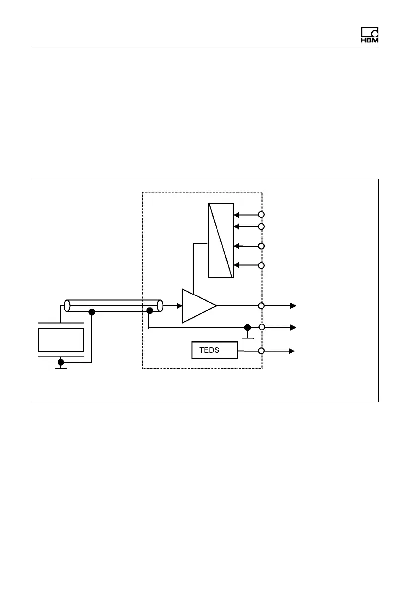
Piezoelectric
force transducer
Charge amplifier
External supply voltage
0V
DC
RANGE 1/RANGE 2
MEASURE/RESET
Output voltage
-10 … +10 V
DC
TEDS
0V
DC
Fig. 5.9 Block diagram of piezoelectric measurement chain, example with external
supply voltage
The measurement channel of the MP85A process controller must be set to
10V (PME Assistant, “Transducer” menu). Before starting a measurement,
reset the charge amplifier (pin 3): MEASURE/RESET. With an input voltage of
0V at pin 3, the charge amplifier is in MEASURE mode. If a voltage of 24 V is
present at pin 3, the charge amplifier switches to RESET.