Switch test (EASYswitch)
MP85A A0293_06_E00_03 HBM: public 87
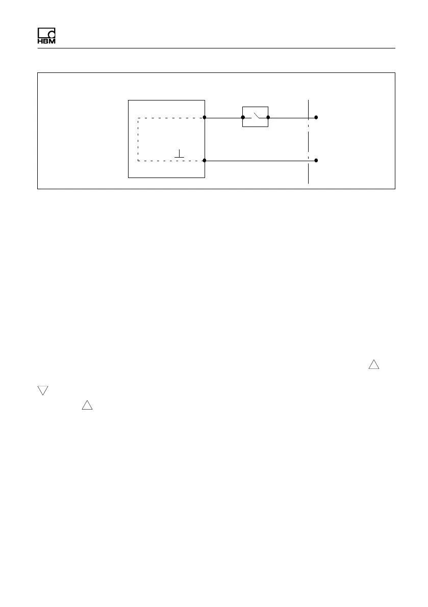
IN 3
IN
MP85A process controller
Screw terminal 3
Switch event/test specimen
24 V (10 … 30V)
0 V
Fig. 9.2 Connection of control input/switch test input
Entry and exit sides are not needed for the switch test window. You can moni
tor this with additional progress windows.
The switch coordinates displayed in the switch test window, i.e. the coordinates
at which the switch changes state, are stored in the statistics. In addition, “No
switching” is signaled for OK or NOK, when the switch has not change its state
or the switching process is repeated because of multiple switching (chatter).
Switch windows can also be parameterized as windows with defined
sequences. This ensures that on/off switching processes are handled in the
correct sequence. Evaluation follows at the end of the process, i.e. you cannot
then select evaluation in real time.
In the graphs, IX:1, the number of the digital input and 1, and the symbol on
the curve are displayed at the switching times for making; Ix:0 and the symbol
are displayed for breaking. If the switch at digital input 1 has closed, for
example, I1:1 is shown on and above the curve (see diagram on page 85).
Repeated switching (chatter)
The EASYswitch version includes analysis for detecting unwanted repeated
switching (chatter) of an electrical switch.
Chatter is detected and the switching window test is assessed as NOK if the
switch-on or switch-off process takes place two or more times within the switch
test window defined by the user.
The switching operations must be longer than one millisecond in order to be
detected; in this case they are displayed as a triangle in the graphic view of the