39
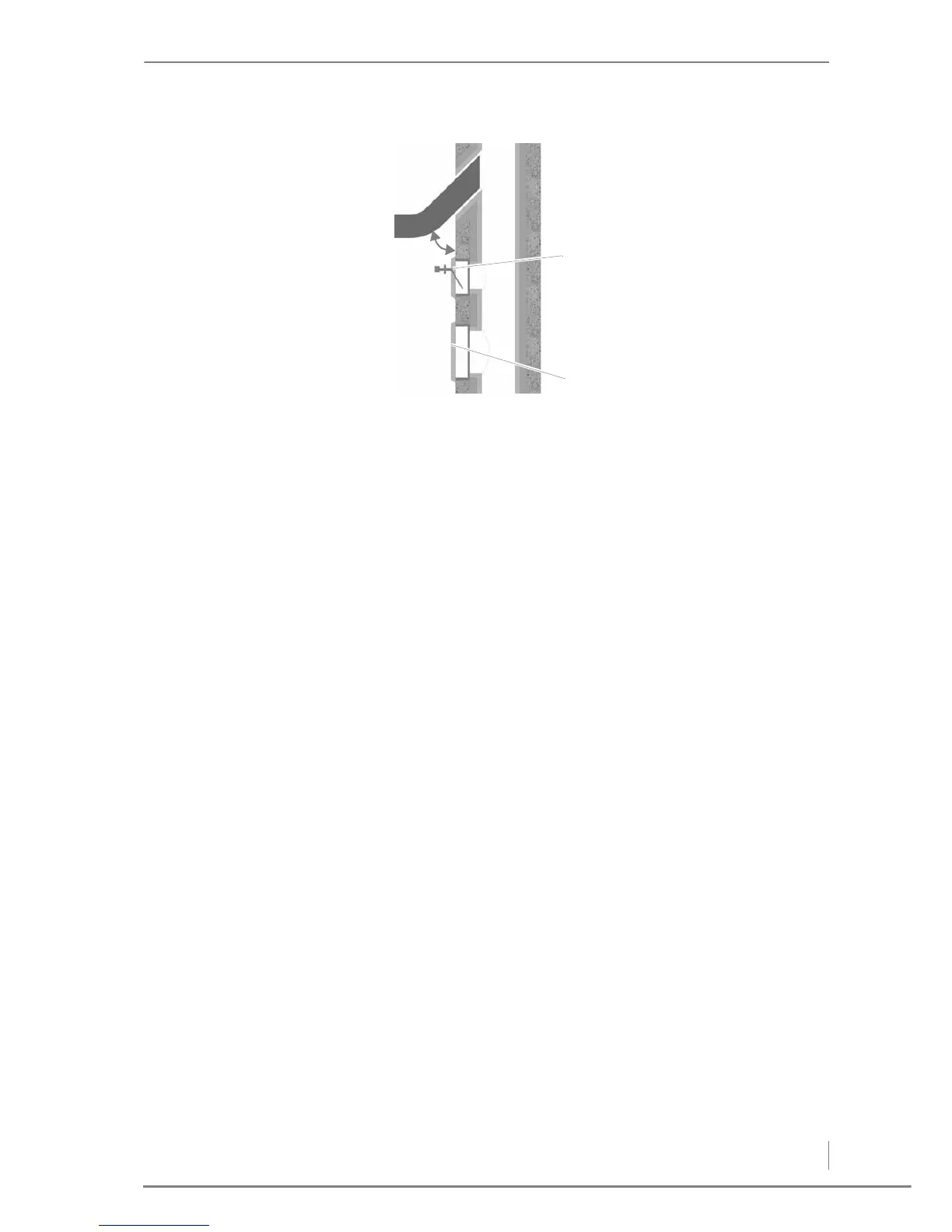
1 Auxiliary air unit, at least 0.5 m above cleaning opening
2Cleaning hatch
A) Angle to the chimney approx. 30° - 45°
The following should also be considered:
• The connecting piece may not protrude into the chimney.
• If the system flue pipe has a larger diameter than the chimney, the
connecting piece must reduce to the diameter of the connection.
In this case, the connecting piece should taper as gently as
possible.
• Use arcs rather than elbows, whereby the radius of the arc may not
be less than the diameter of the pipe.
• Chimney should be vertical and straight, if possible without bends
(take particular care in older buildings).
• All of the cleaning and measurement hatches on the chimney
must be tightly sealed.
• To reduce the entry of additional cold air, only one heat producer
should be attached to each chimney.
ELECTRICAL SYSTEM
The terms of 2006/95/EC (low voltage guidelines) must be followed
for the electrical connections to the system.
No electrical installations, such as power sockets, distribution
sockets, lights or light switches are allowed in the pellet bunker. Any
lights must be suitable for use in areas at risk of explosion. The VDE
regulations for rooms with a risk of dust explosion must be followed.
✎ The required connection values are listed in chapter “3 Mode of
operation”, section “3.3 Technical data”.
Figure 4/12 - Connection to the chimney