4 Planning and installation – HDG hydraulic systems
79
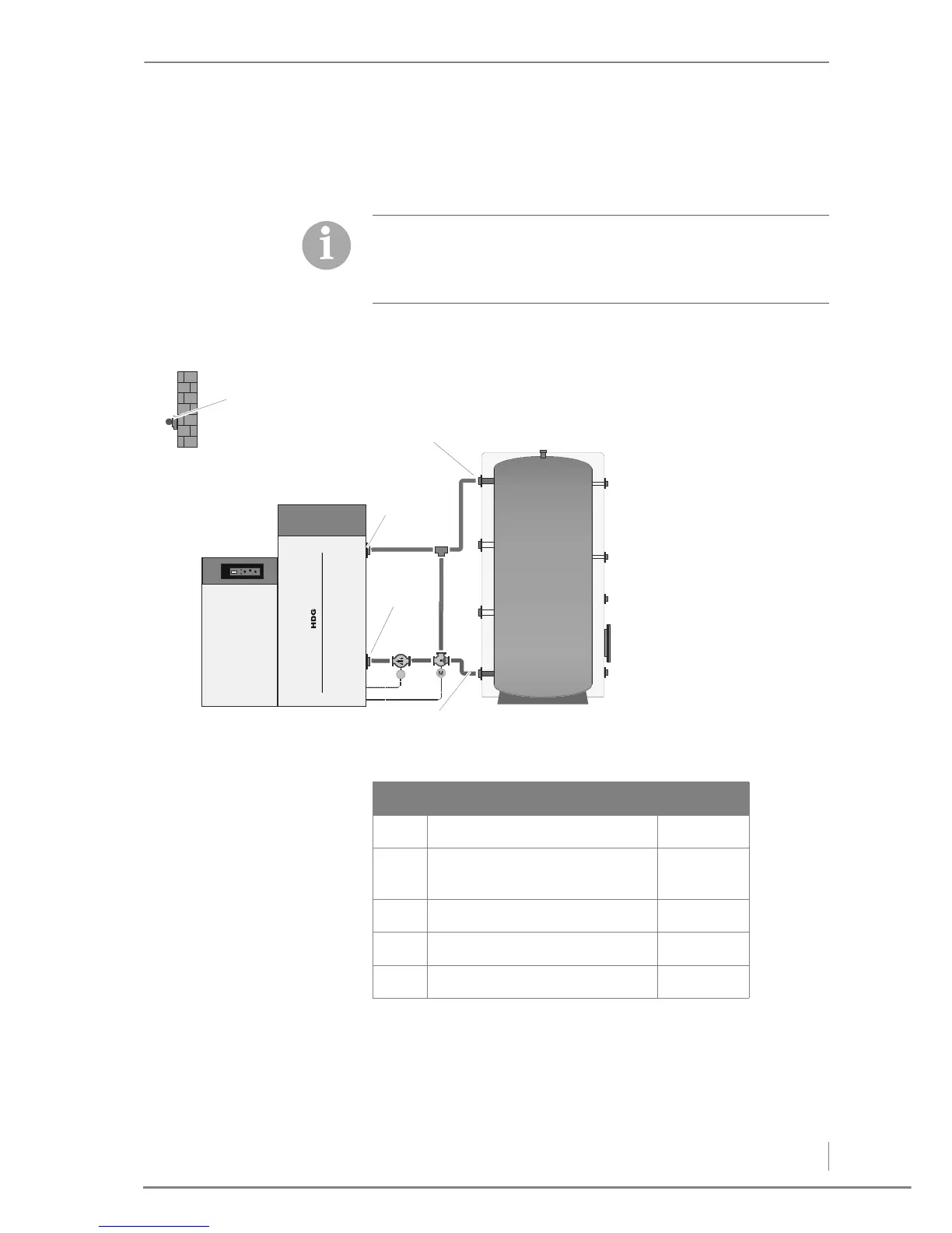
4.10 HDG hydraulic systems
HYDRAULIC SYSTEM 0
The following pages contain the available hydraulic diagrams with
the corresponding connection on the circuit boards. A brief
description of the menu system is also provided in table form for
the selection of the respective hydraulic diagram.
Figure 4/73 - Hydraulic system 0
HDG Pelletronic Connection
OTS Outdoor temperature sensor 40 / 41
ST Supply temperature sensor
(boiler temperature)
48 / 49
RT Return temperature sensor 46 / 47
Bt Buffer top sensor 44 / 45
Bb Buffer bottom sensor 42 / 43