48
INSTALLING THE SENSORS
SUPPLY TEMPERATURE SENSORS
1. Insert the supply temperature sensor (1), with the red mark on the
cable, in the left hand side (as viewed from the front) immersion
sleeve (2) located on the back side of the boiler.
C
APILLARY SENSOR OF THE
SAFETY TEMPERATURE LIMITER
2. Insert the capillary sensor (4) of the safety temperature limiter in
the immersion sleeve of the supply temperature sensor (2).
3. Fasten the supply temperature sensor (1) and the capillary sensor
(4) with the spring clip (3).
✓ The supply temperature sensor and the capillary sensor of the
safety temperature limiter have been installed.
R
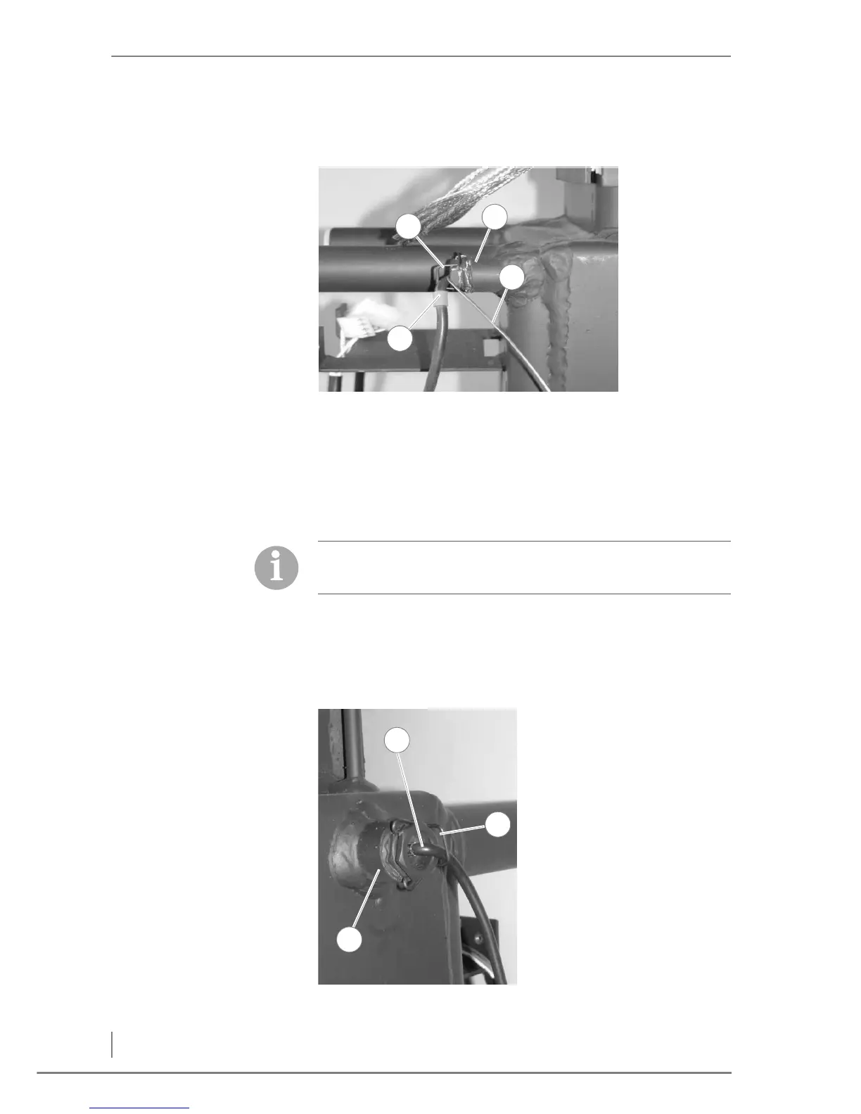
ETURN TEMPERATURE SENSOR
Figure 4/17 - Installing the supply sensors
The capillary sensor is found upon delivery in the control cabinet.
✎ See Figure 4/23 - Installing the control cabinet.
4. Insert the return temperature
sensor (1), with the blue mark,
in the right hand side (as
viewed from the front)
immersion sleeve (2) located
on the right side of the boiler.
5. Fasten the return sensor (1) in
place with the spring clip (3).
6. Feed the silicone-coated
cable of the return sensor (1)
to the electronics on the left
hand side of the boiler.
✓ The return sensor has been
installed.
Figure 4/18 - Installing the return sensor