88
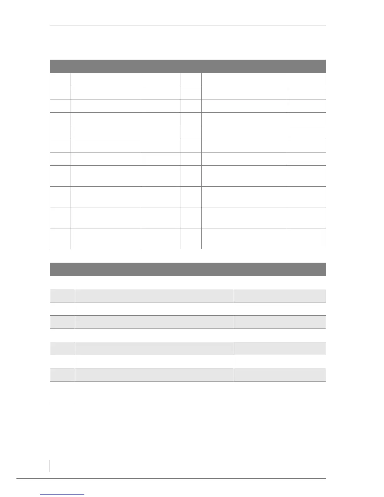
HDG Hydronic Connection Connection
Inputs (sensors) Outputs (units)
F1 not assigned A1 Solar pump H34
F2 Hot water tank top H11 / H12 A2 Buffer tank pump H33
F3 Hot water tank bottom H13 / H14 A3 Hot water pump H28
F4 Supply CCT1 H7 / H8 A4 Heating circuit pump CCT1 H27
F5 Supply CCT2 H9 / H10 A5 Heating circuit pump CCT2 H26
F6 not assigned A6 not assigned
F7 not assigned A7 Heating circuit mixer CCT1
open
H31
F8 not assigned A8 Heating circuit mixer CCT1
closed
H32
F9 not assigned A9 Heating circuit mixer CCT2
open
H29
F10 Solar collector
temperature
H19 / H20 A10 Heating circuit mixer CCT2
closed
H30
No. Description Notes
8-01 Activate hydraulic system 4
8-02 Select buffer type
8-04 Set the heating system for heating circuit 1
8-05 Set the heating system for heating circuit 2
8-07 Option of activating a hot water tank
8-08 For solar heating settings
8-10 Option of also activating an oil-fired boiler
8-12 Option of activating an additional heating circuit module
8-00 The settings for the hydraulic system have been
completed