10
Back panel
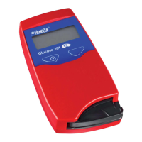
FIGURE 1-3
The following items are found on the back
panel of the Analyzer.
• Power inlet(1) for the Power Adapter
• Power + USB signal inlet(2) for
connection to the Docking Station
• Built-in Barcode Scanner(3)
• IR Transmitter/Receiver(4) for data
transfer to/from the Docking Station
Data can be transmitted between the
Analyzer and the Docking Station in dierent
ways depending on which version of
Docking Station is used and how the
Docking Station is connected to Software:
• Via USB using the Power + USB signal
inlet (2), if the Docking Station
communicates with the DMS Software via
USB or if the Docking Station is labelled
“+” and communicates with the DMS
Software via LAN
• By means of IR-light using the IR
Transmitter/Receiver (4), if the Docking
Station is NOT labelled “+” and
communicates with the DMS Software via
LAN
1 Power inlet (for Power Adapter)
2 Power + USB signal inlet (for Docking Station)
3 Barcode Scanner
4 IR Transmitter/Receiver
3
4
1
2
 Loading...