11
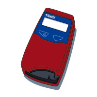
FIGURE 1-4
Settings can be transmitted between two
Analyzers via the IR Transmitter/Receiver (see
section 3.6 Infra Red). The Analyzers have to
be out of the Docking Stations and
positioned with the IR Transmitter/
Receivers(4) facing each other.
The Power inlet(1) for the Power Adapter
can only be used when the Analyzer is
separated from the Docking Station. When
the Analyzer is placed in a Docking Station,
this inlet will be blocked and the Analyzer
receives power via the Power + USB signal
inlet(2).
The combined Power + USB signal inlet(2) is
not a standard USB port, but a special
connector which fits the corresponding
connector on the Docking Station.
The IR Transmitter/Receiver(4) is located
inside the casing of the Analyzer.
Do not cover or block the items on the back
panel; doing so may result in malfunction.
1 Power inlet (for Power Adapter)
2 Power + USB signal inlet (for Docking Station)
3 Barcode Scanner
4 IR Transmitter/Receiver
3
4
1
2
 Loading...