Introduction
Chapter 3: Theory of Operation
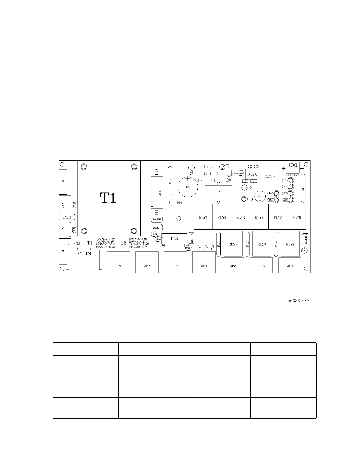
Page 3 - 2 Basic Care™ Bed Service Manual (man336)
Transformer Configurations
The electric Basic Care™ Bed permits eight different input source voltages
using two transformers and various connector positions on the control board
(see figure 3-1 on page 3-2).
The control board is configured for either T1 or T2 transformers.
Figure 3-1. Transformer Configurations
For the correct transformer configuration, refer to table 3-1 on page 3-2.
Table 3-1. Transformer Configurations
Input Source Voltage Transformer JP9 or JP10 Position JP8 Position
100 V T1 JP10 LO
110 V T2 JP10 LO
115 V T1 JP10 HI
127 V T2 JP10 HI
200 V T1 JP9 LO
220 V T2 JP9 LO