41
────────────────────────────────────────────────────
3.5 PASS or FAIL Determination
────────────────────────────────────────────────────
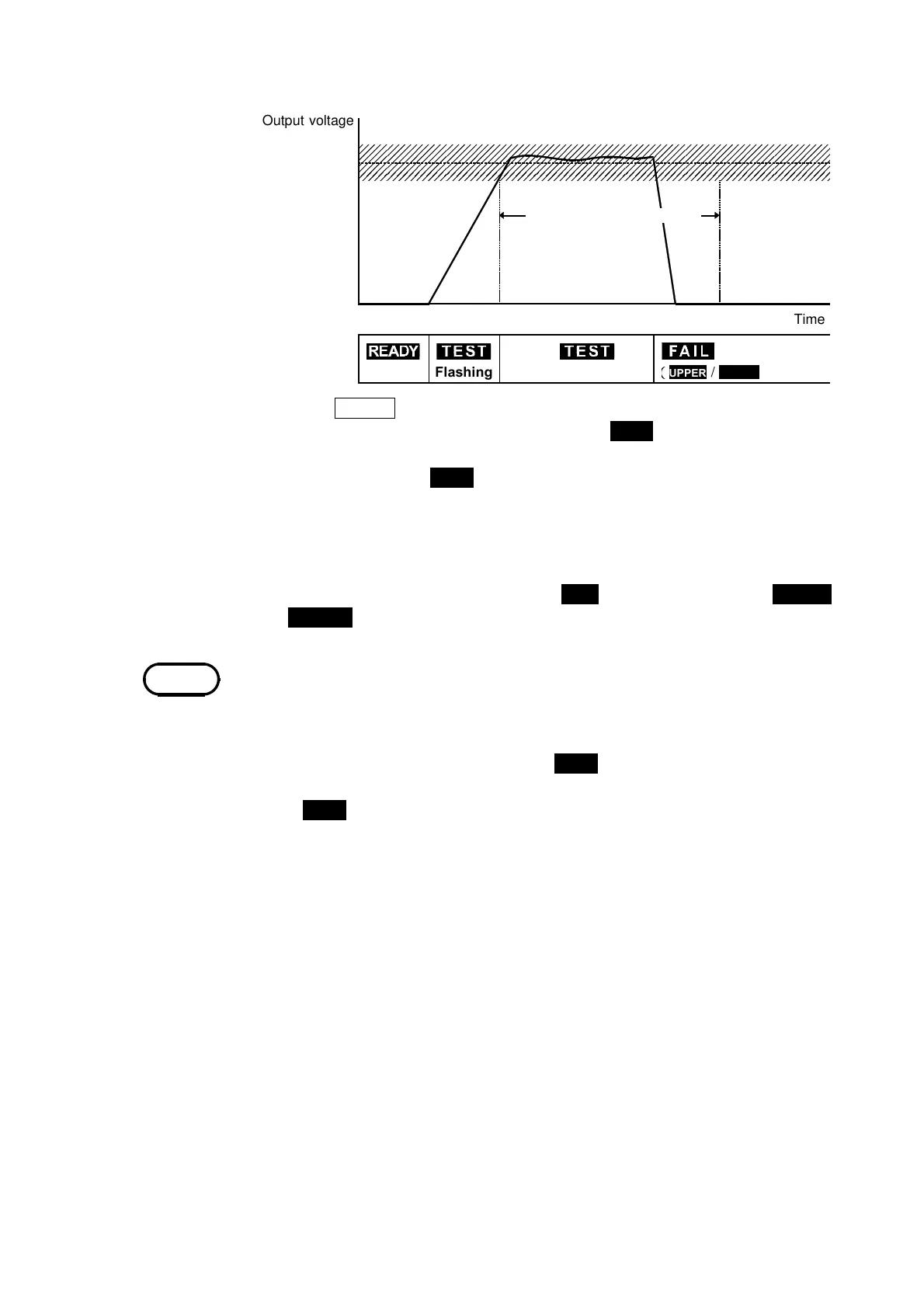
Out
ut volta
e
Time
Flashin
UPPER
/
LOWER
Testin
time when it set u
Comparative
volta
evalue
NOTE
Flow of FAIL determination
(1) Press the
START
key to start a test.
(2) When a comparative-voltage value has been set, TEST flickers until the output
voltage switches to the comparative-voltage range. Once the output voltage
switches to this range, TEST lights up and the reduction timer begins counting
down the test time.
(3) A voltage continues to be output until the test time elapses. If the measured
current deviates from the upper- or lower-level value during this period, the unit
switches to the FAIL state.
(4) Once a switch is made to the FAIL state, FAIL lights up, together with UPPER
or LOWER. The unit stops outputting a voltage and the reduction timer stops.
・
If the current generated is several times as large as the upper-level value, for
example when the test object is short-circuited and etc., a circuit promptly cuts
off the high voltage, thereby switching the unit to UPPER FAIL before measuring
the current.
・
If a comparative-voltage has not been set, TEST does not flicker.
If the optional "Voltage Comparator Position" function is set to "1: End of test
time", TEST does not flicker.