81
────────────────────────────────────────────────────
6.1 External I/O Terminal
────────────────────────────────────────────────────
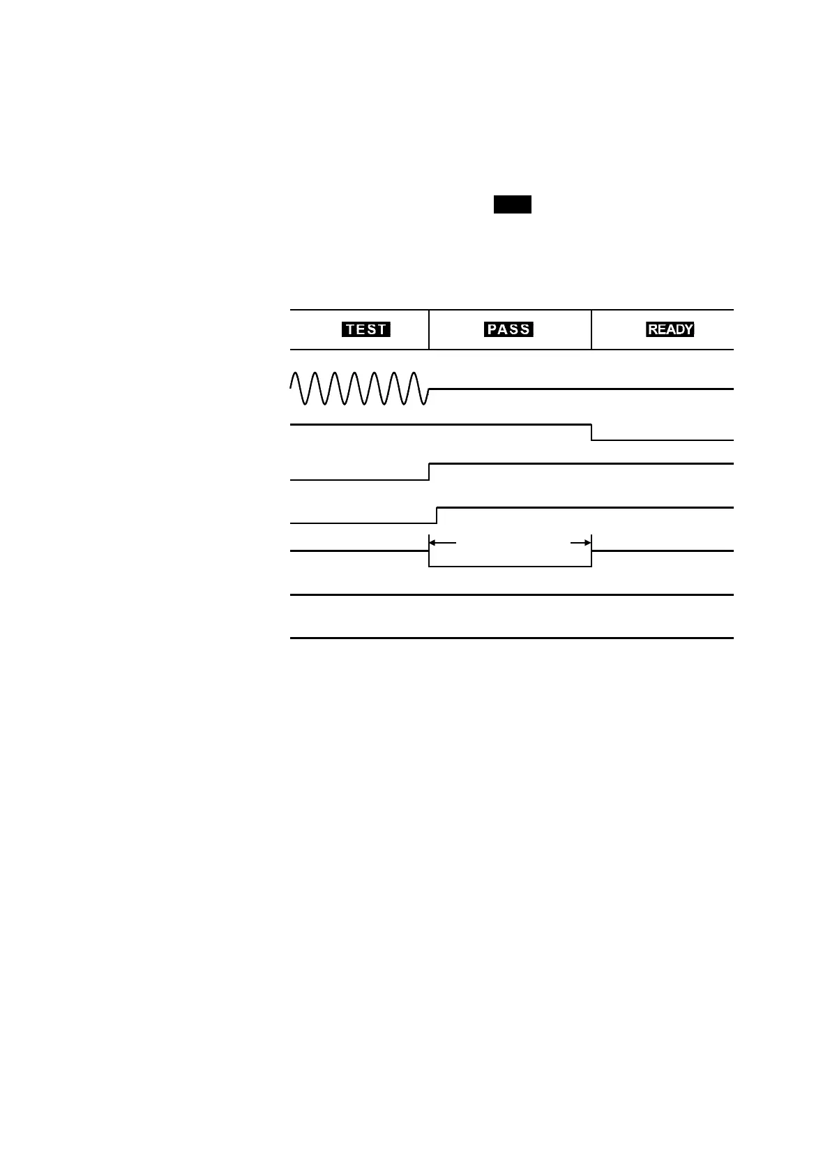
450 ms < t < 550 ms
Voltage Output
READY
_______
TEST
_____
H.V.ON
_______
PASS
______
U-FAIL
_______
L-FAIL
______
(2) Timing chart during a test decision
The figure shows the timing chart of the unit in PASS state after a test. In PASS
state, the TEST
_______
signal indicates HI.
The H.V.ON
_________
signal remains at LO provided that the voltage between the output
terminals remains unchanged, as the signal is synchronized with the DANGER
lamp. Once the voltage reaches 0, the signal changes to HI.
The PASS
_______
signal changes according to the
PASS
indicator on the fluorescent
display. If the PASS hold function is enabled, the PASS
_______
signal continues to
indicate LO until the function is disabled.
When the Hold function is disabled or the unit automatically returns to the READY
state, the PASS
_______
signal becomes HI and the READY
_________
signal becomes LO.
With UPPER-LOWER FAIL, which is activated when the output voltage fails to
reach the comparative-voltage value, the U-FAIL
_________
and L-FAIL
_________
signals are at LO.
Even in the FAIL state, when UPPER FAIL is activated, the U-FAIL
_________
signal
becomes LO. Similarly, with LOWER-FAIL, the L-FAIL
_________
signal becomes LO. When
the FAIL Hold function is set, the signal remains at LO until the Hold function is
disabled. When the Hold function is disabled or the unit automatically returns to the
READY state, the PASS
_______
signal becomes HI and the READY
_________
signal becomes LO.