7.4.3 Table board 2 for YUTAKI S and YUTAKI S COMBI
7.4.3.1 Indoor/outdoor communication wiring (TB2) / ATW-RTU Communication / Central Devices
Communication
• The transmission is wired to terminals 1-2.
• The H-LINK II wiring system requires only two transmission cables that connect the indoor unit and the outdoor unit in case of split
system and also connect the indoor unit with ATW-RTU or Central devices like ATW-TAG-02, ATW-KNX-02 and ATW-MBS-02.
1
1
2
2
Indoor unit
Outdoor unit ATW-RTU /
Central Devices
• Use twist pair wires (0.75 mm²) for operation wiring between outdoor unit and indoor unit. The wiring must consist of 2-core wires
(Do not use wire with more than 3 cores).
• Use shielded wires for intermediate wiring to protect the units from noise interference, with a length of less than 300 m and a size
in compliance with local codes.
• In the event that a conduit tube for eld-wiring is not used, x rubber bushes to the panel with adhesive.
! CAUTION
Ensure that the transmission wiring is not wrongly connected to any live part that could be damaged the PCB.
Input and output terminals give the possibility to congure the installation according to the needs of the user. The default settings
and I/O terminals reach most of the options necessary for an optimal performance of the system. Additionally, the settings can be
modied through the unit controller, and input/output terminals can be used, if required, to have additional options.
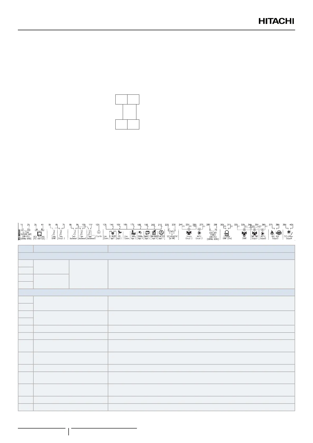
7.4.3.2 Summary of terminal board connections YUTAKI S - RWM-(2.0-10.0)(N/R)1E
Mark Part name Description
TERMINAL BOARD 1 (TB1)
N
1~ 230V 50Hz
3N~ 400V 50Hz Main power supply connection
L1
L2
-
L3
TERMINAL BOARD 2 (TB2)
1
H-LINK commutation
The H-LINK transmission has to be done between the indoor unit and the terminals 1-2 of either
outdoor unit, ATW-RTU or any other central device.
2
3
H-LINK communication for remote
control switch
Terminals for the connection of the YUTAKI unit controller.
4
5 DHW tank’s thermistor The DHW sensor is used to control the temperature of the domestic hot water tank.
6 Common thermistor Common terminal for thermistor.
7
Thermistor for water outlet
temperature of second cycle
The sensor is used for the second temperature control and should be positioned after the mixing
valve and the circulation pump.
8
Thermistor for water outlet
temperature after hydraulic separator
Water sensor for hydraulic separator, buffer tank or boiler combination.
9 Common thermistor Common terminal for thermistors.
10
Thermistor for swimming pool water
temperature
The sensor is used for the swimming pool temperature control and should be positioned inside
plate heat exchanger of the swimming pool.
11
Thermistor for second ambient
temperature
The sensor is used for the second ambient temperature control and it should be positioned
outdoors.
12 Earth Earth connection for the 3 way valve and water pump
13 Common line Terminal Line common for input 1 and input 2.
ELECTRICAL AND CONTROL SETTINGS
PMML0575 rev.2 - 03/2022
110
 Loading...