ENGLISH
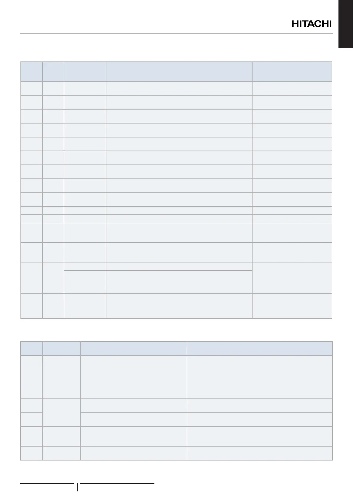
12.1.2 Alarms for YUTAKI CASCADE CONTROLLER ATW-YCC-(01/02)
Alarm
Code
Retry
Stop
Code
Origin Detail of Abnormality Main Factors
03 - Communication Lost communication with all slave YUTAKI Units
Loose, disconnected, broken or
short-circuited connector
15 - Indoor Water Circuit 2 thermistor abnormally (THMwo2)
Loose, disconnected, broken or
short-circuited connector
16 - Indoor Water DHW thermistor abnormally (THMdhwt)
Loose, disconnected, broken or
short-circuited connector
17 - Indoor Auxiliary sensor 2 thermistor abnormally (THMaux2)
Loose, disconnected, broken or
short-circuited connector
18 - Indoor Auxiliary sensor 1 thermistor abnormally (THMaux1)
Loose, disconnected, broken or
short-circuited connector
25 - Indoor Auxiliary sensor 3 thermistor abnormally (THMaux3)
Loose, disconnected, broken or
short-circuited connector
40 - Indoor Incorrect LCD setting
Current LCD conguration does not
allow proper operation
60 - Slave unit
All slave units are in alarm state or there is no communication.
Alarm release, when issue disappears
Slave unit alarm
73 Indoor Mixing over-temperature limit protection for Mixed circuit.
Circuit 2 supply temperature >
Target temperature + offset
74 P74 Indoor Unit over-temperature limit protection Two > Tmax +5K
75 - Indoor Freeze Protection by Cold water inlet, outlet temperature detection
77 - Indoor-LCD Receiver Communication failure
No Opentherm/Hlink
communication for a continuous
period of 10 minutes.
78 Indoor-LCD RF Communication failure
There is no communication for 1
hour with on or two RF receives
which are bound to the RF-Bridge.
80 -
Indoor LCD H-link RCS transmission error No H-link communication for a
continuous period of 1 minute
between Indoor and LCD User
control by connection wiring
(breaking, wiring error, etc.)
LCD (If no H-LINK RCS has no power)
21X - Slave unit
Module X is in alarm state. X stands for the module number. A
module is determined to be in alarm state in case that module is in
alarm or YUTAKI CASCADE CONTROLLER lost communication
with specic module.
Slave unit alarm
12.1.3 Alarms for Outdoor units
Code
number
Category Type of abnormality Main cause
2 Outdoor unit
Activation of protection device
(high pressure cut)
Activation of PSH, locked motor, abnormal operation in the power
supply phase.
Failure of fan motor, drain discharge, PCB, relay, oat switch
activated.
(Pipe clogging, excessive refrigerant, innert gas mixing, fan motor
locking at cooling operation)
3
Transmission
Abnormal transmission between outdoor and
indoor units
Incorrect wiring. Loose terminals, Failure of PCB. Tripping of fuse.
Power supply OFF.
4
Abnormal transmission between inverter PCB
Transmission failure between inverter PCBs. (Loose Connector,
Wire Breaking, Blowout of Fuse).
5 Power supply
Reception of abnormal operation code for
detection of power source phase
Power source with abnormal wave pattern. Main power supply
phase is reversely connected or one phase is not connected.
6 Voltage
Excessively low voltage or excessively high
voltage for the inverter
Voltage drop in power supply. Incorrect wiring or insufcient
capacity of power supply wiring.
TROUBLESHOOTING
PMML0575 rev.2 - 03/2022
317
 Loading...