115
Electrical wiring
SMGB0066 rev.0 - 12/2009
Controller pack
Service Manual
4
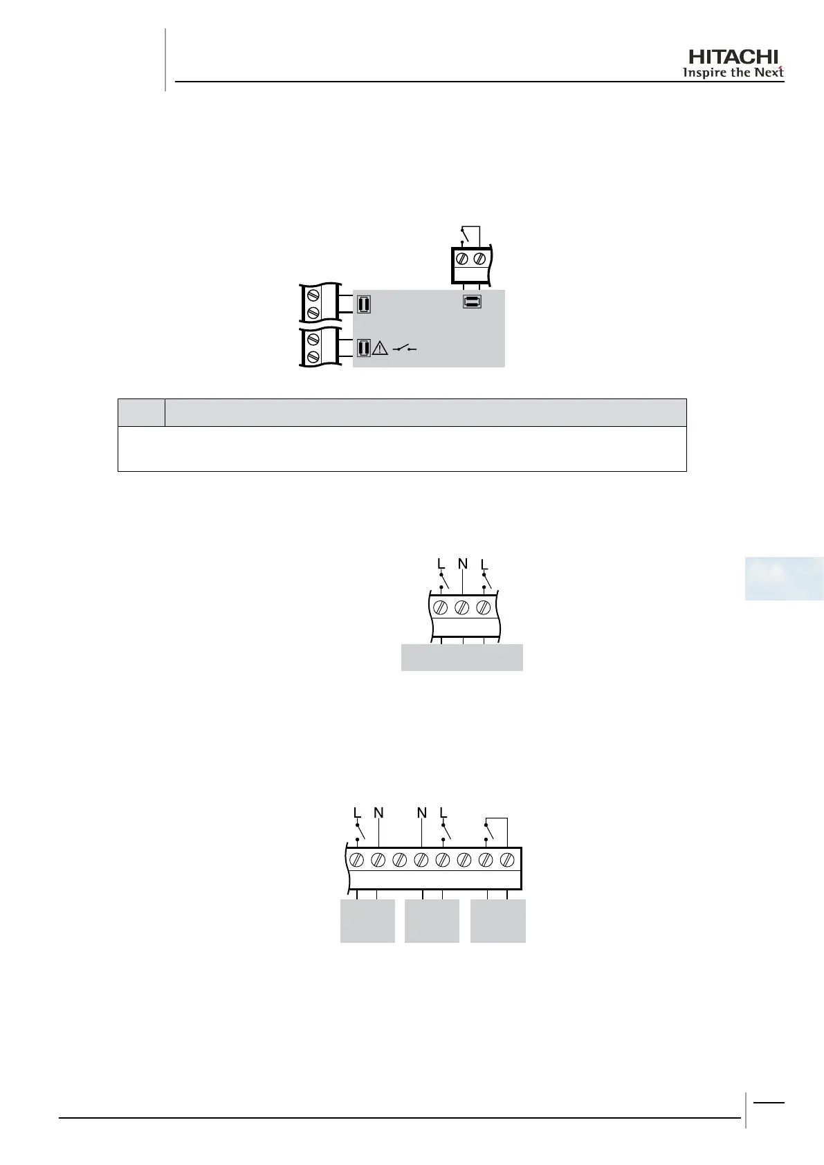
The System Controller controls the heat pump outlet water temperature by a 4-20mA signal. When there is no demand for
theheatpumptobeon,theSystemControllerdirectlyswitchestheheatpumpoff.TheheatpumpcansignaltotheSystem
Controller when it has a fault so that a fault code can be displayed and appropriate action taken.
21
6
5
31
TERMINAL
BLOCK C
4-20mA
TERMINAL BLOCK A
Heat Pump
/NO
FFO
2
1
note
The 4-20mA signal is polarity-sensitive. Connect the wires as shown. Please refer to heat pump installation -
manual for terminal connections.
Inamono-energeticsystem(CONF2),theelectricheaterisusedifrequiredtoincreasethesupplywatertemperature.
P19 Waiting time for boiler/electric heater
9
8
7
Output 1
N
Output 2
InaBi-ValentSystem(CONF3,4,5),theboilerisusedwhentheheatpumpcannotachievethedesiredsupplytemperature
onitsown.Settheminimumonandofftimes(P17andP18),accordingtoboilertype,topreventinefcientshort-cycling.
P17 Boiler Minimum ON Time
P18 Boiler Minimum OFF Time
P19 Waiting time for boiler/electric heater
12
11
10
9
8
7
6
5
Boiler
ON/OFF
Boiler
Pump
(CONF3)
Boiler
Pump
(CONF4)
TERMINAL
BLOCK A

 Loading...


