255
RHUE-(3~6)A(V)HN
SMGB0066 rev.0 - 12/2009
Servicing
Service Manual
9
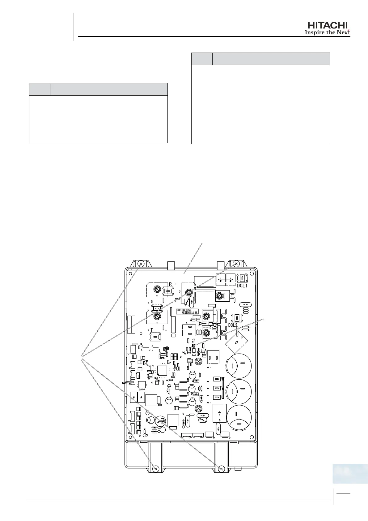
The DIP-IPM is equiped in the RHUE-(3~6)AVHN units.
danger
Electrical hazard. Risk of death. -
Check that the LED201 (red) located on the inverter -
module is OFF when opening the P-mounting plate.
Do not touch the electrical components when LED201 -
(Red) located on the inverter module is ON in order to
avoid an electrical shock.
Disconnect all the wirings connected to the module. 1.
Disconnectthewiringsoftheterminals+,-,U,V,W -
Disconnect all the wirings connected to the module. 2.
Removethefour(4)xingscrewsontheDIP-IPM -
module to remove it.
note
Several hazards. Risk of malfunction. -
Identify the terminal numbers with mark band. When -
reassembling, the terminals have to be connected to the
correct numbers . If incorrectly connected, malfunctions
or damages will occur.
Check to ensure that the electrical wires will not be -
caught between the mounting electrical components and
the mounting plates when the PCB is remounted.
Apply silicon grease evenly on the whole rear side of the -
diode module and the transistor module when mounting.
Silicon grease is available as a eld-supplied accessory.
DIP-IPM module
4xingscrews
LED201

 Loading...


