Controller pack
Service Manual
144
Yutaki unit PCB
SMGB0066 rev.0 - 12/2009
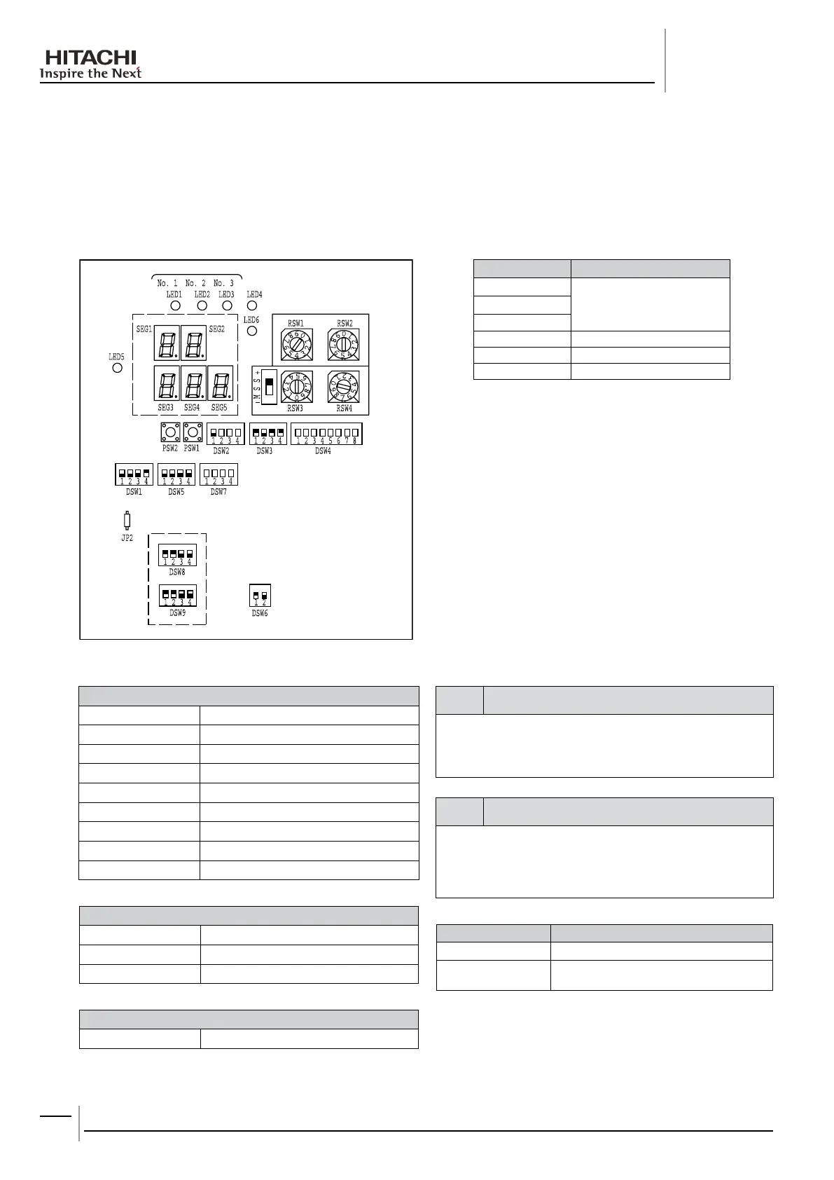
ThePCBintheYutakiunitoperateswithnineDIPswitches,sixLEDsandtworotaryswitches.Thelocationisasfollows:
LED 1
Power supply indication
LED 2
LED 3
LED 4 Operation status indication
LED 5 Alarm indication
LED 6 Setting mode indication
DSW1 Optional functions
DSW2 Unitcontrolconguration/UnitHP
DSW3 Unitcontrolconguration
DSW4 Unitmodelconguration
DSW5 Not used
DSW6 End resistance / Fuse recovery
DSW7 Unitcontrolconguration
DSW8 Setting Pd Pressure Sensor Type
DSW9 Setting Ps Pressure Sensor Type
RSW1 & RSW2 Heating setting temperature
RSW3 & RSW4 Not used
SSW UP=”+ Temp.” / DOWN=”-Temp.”
JP2 Cut ⇒ Re-Start after power failure
note
The mark “ - ” indicates position of dips switches. Figures show
setting before shipment or after selection.
Not mark “ - ” indicates pin position is not affecting.
note
Before setting dips switches, rstly turn off power source and -
set the position of the dips switches. If the switches are set
without turning off the power source, the contents of the setting
are invalid.
SEG1 / SEG2 Unit Status
SEG3,SEG4,SEG5
Discharge and Suction pressure value
alternatively
Press the PSW2 more than three seconds to change the
status display mode.
Press the PSW1 and PSW2 together more than three
seconds to switch to alarm history mode.

 Loading...


