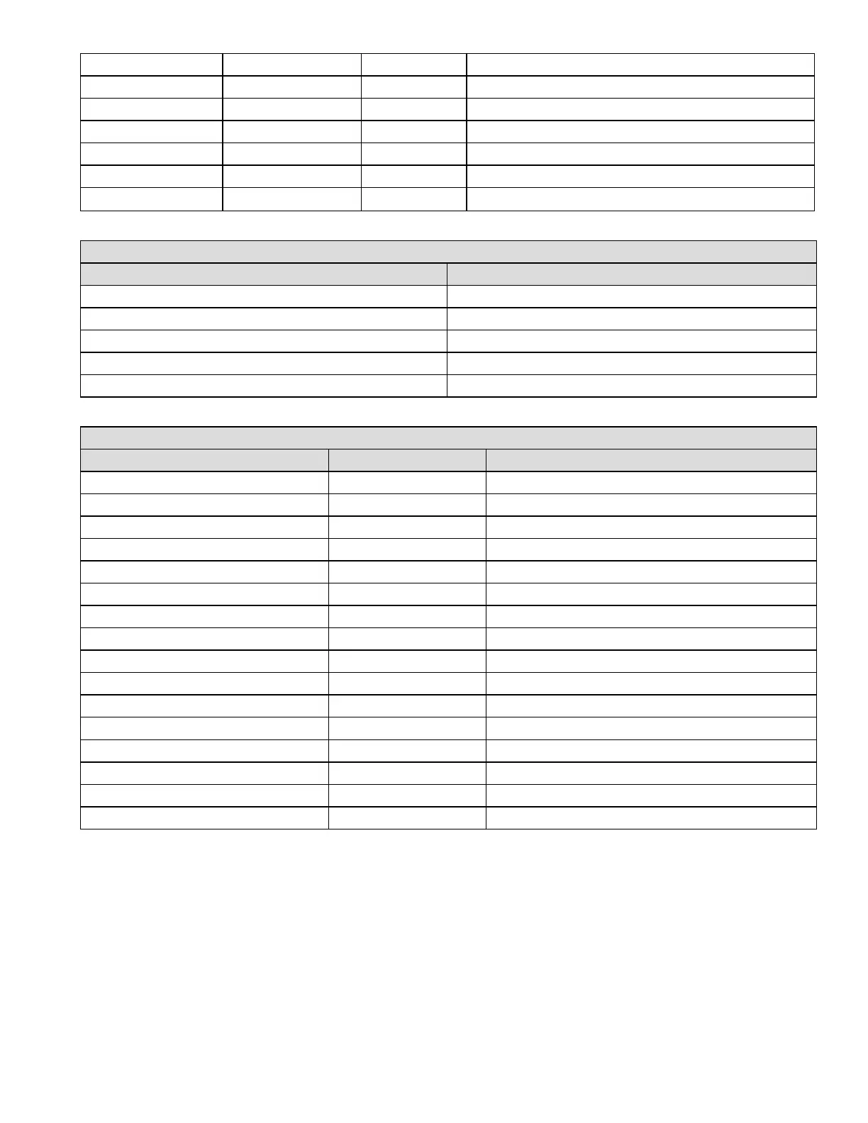
40045 40045 int16 Internal 5.0 VDC supply (mV)
40075 40081 char [14] Detector serial number (string)
40084 40084 int16 Hardware revision number
40085 40085 int16 Software revision number
40103 40104 float32 Sensitivity configuration (0.3)
40105 40105 float32 Alarm Verification Time (seconds)
40123 40123 word16 Relay configuration (see Table 3)
Table 2. Modbus holding register 40007 will have the following values:
Value Meaning
1 Normal monitoring
3 Inhibited
7 In warning MFIt
8 In Instrument Flt
Other For future expansion
Table 3. Modbus holding register 40123 contains the logical OR of following bits:
Bit Number Bit Value Condition
0 0x0001 reserved for future use
1 0x0002 reserved for future use
2 0x0004 reserved for future use
3 0x0008 reserved for future use
4 0x0010 Relay 2 is normally energized
5 0x0020 Relay 3 is normally energized
6 0x0040 reserved for future use
7 0x0080 reserved for future use
8 0x0100 reserved for future use
9 0x0200 reserved for future use
10 0x0400 Always on
11 0x0800 Relay 3 is warning instead of alarm2
12 0x1000 reserved for future use
13 0x2000 reserved for future use
14 0x4000 reserved for future use
15 0x8000 reserved for future use
Honeywell®FS24XPlus™ | User Manual
101

 Loading...


