Performance
Power-Up
During power-up initialization, the device will not respond to HART® commands, and the analog
output is set at 4.0 mA.
Command Response Times
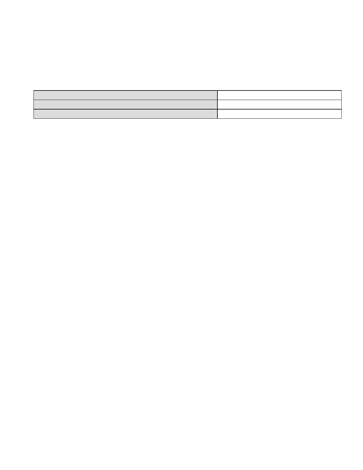
Approximate command response times are listed in the following table:
Minimum 20ms
Typical 50ms
Maximum 100ms
Busy and Delayed-Response
The transmitter may respond with "busy" status if a further command is received while self-test is
underway.
Delayed-response is not used.
Long Messages
The largest data field used is in the response to Command 21: 34 bytes including the two status
bytes.
Non-Volatile Memory
EEPROM is used to hold the device’s configuration parameters. New data is written to this memory
immediately on execution of a write command.
Modes
Fixed current mode is implemented, using Loop current mode (Enable – Point to Point / Disable-
Multi-drop). This mode is not cleared by power loss or reset.
Write-protection and User controllable Damping are not supported.
Honeywell®FS24XPlus™ | User Manual
99

 Loading...


