Honeywell® FS24XPlus™ | User Manual
23
Commissioning the Detector
Apply power to the FS24XPlus™ Flame detector. This can be done in a field workshop before
installation.
The HALO flash pattern activates during boot-up: Red, Green, and Blue repeatedly, for about 15
seconds followed by solid Yellow for two minutes indicating inhibit state.
Note: Heaters are used during extreme cold to bring the internal electronics up to a minimum temperature. During this time, which
can last up to 30 minutes, the internal microcontrollers are not running, halo will be off, and the current loop will report less than
1.5 mA.
The HALO patterns during operation are shown in the Specifications section.
Analog Output: Flame Detected
The 4-to-20mA current loop is connected on two terminals marked "mA+ " and "mA-".
This output corresponds to the Primary Variable. HART® Communication is supported on this loop.
The FS24XPlus™ is equipped with a 4-20 mA loop output which can operate in source, sink and
isolated mode. Source, sink, and isolated modes are configured by Wiring. This output is a safety-
related output and is compatible for use in SIL 2 applications. Normal operation and alarm
conditions are indicated between 4 to 20 mA.
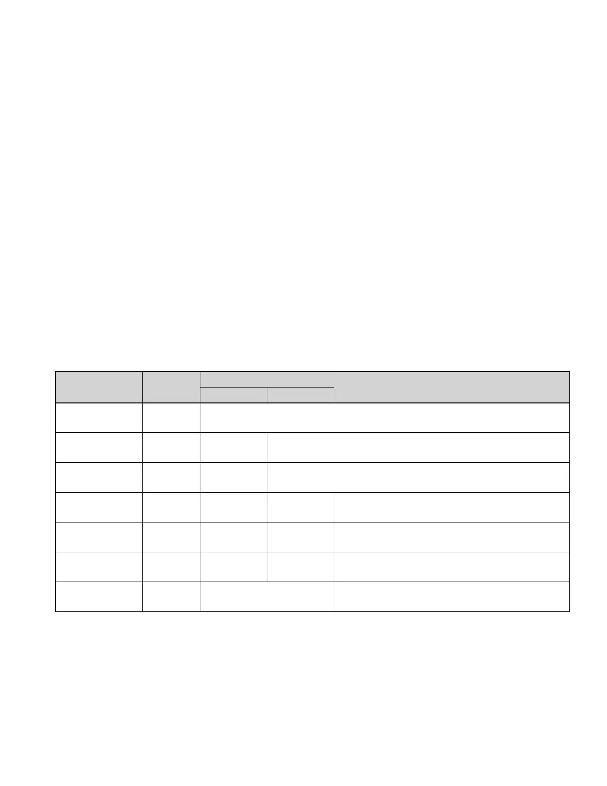
Operational
State
Factory
Default
Configurable Range
Configuration Restrictions
Min Max
Power Fault /
No Power
0.0 mA Not Configurable
Loop Current Value will be 0.0 mA in case of
non-maskable fault state (safe state)
Instrument Fault
State
1.0 mA 1.0 mA 3.6 mA
Not to exceed Inhibit setting - resolution of
setting 0.1 mA
Inhibit State 2.0 mA 1.0 mA 3.6 mA
Greater than or equal to a fault and not to
exceed Warning - resolution of setting 0.1mA
Instrument
Warning State
3.0 mA 1.0 mA 4.0 mA
Greater than or equal to Inhibit - resolution of
setting 0.1mA
Normal
Operation State
4.0 mA 4.0 mA 4.5 mA 4.5 mA for FMM-420 Module Interface
FireAlarm State 16.0 mA 4.0 mA 20.0 mA
Configurable Values are either 4.0 mA, 16.0
mA or 20.0 mA
Verified Fire
Alarm State
20.0 mA Not Configurable

 Loading...


