CHAPTER
9
Appendix 6: Overview of the FS24XPlus™ Modbus
Interface
The FS24XPlus™ Flame detector communicates status using a variety of channels including the
HALO light ring flash pattern, a 4-20 mA current loop with HART®, three relays, RS-485 and USB.
The current loop is designed for use in systems designed for safety integrity level (SIL) 2 as defined
by EN 61508.
The relay outputs are designed for use in SIL 1 systems. The digital interfaces (RS-485 and USB) do
not have any SIL rating but are still useful because of the data they provide.
The USB interface is not accessible when the enclosure is closed and is used for initial set-up or
post event diagnostics or maintenance.
The RS-485 interface can communicate in two modes: either Honeywell® proprietary FP2 or
standard Modbus. The configuration of the detector can be manipulated over USB or RS-485/FP2
but not standard Modbus. This section describes RS-485/Modbus.
Communications Capabilities.
The RS-485 port can be configured for speeds of 9600, 19200, 38400, 76800, or 115200 baud with
a default of 9600 baud. Each byte can have even, odd, or no parity with a default of even parity.
Additionally, each byte can have one or two stop bits with a default of one stop bit. These parameters
are set on the Configure/Fieldbusses tab of Honeywell® FlameManager . After the settings are
changed, the detector must be rebooted before they take effect. The Modbus interface is
implemented entirely as holding registers as listed in Table1. Writing is not permitted.
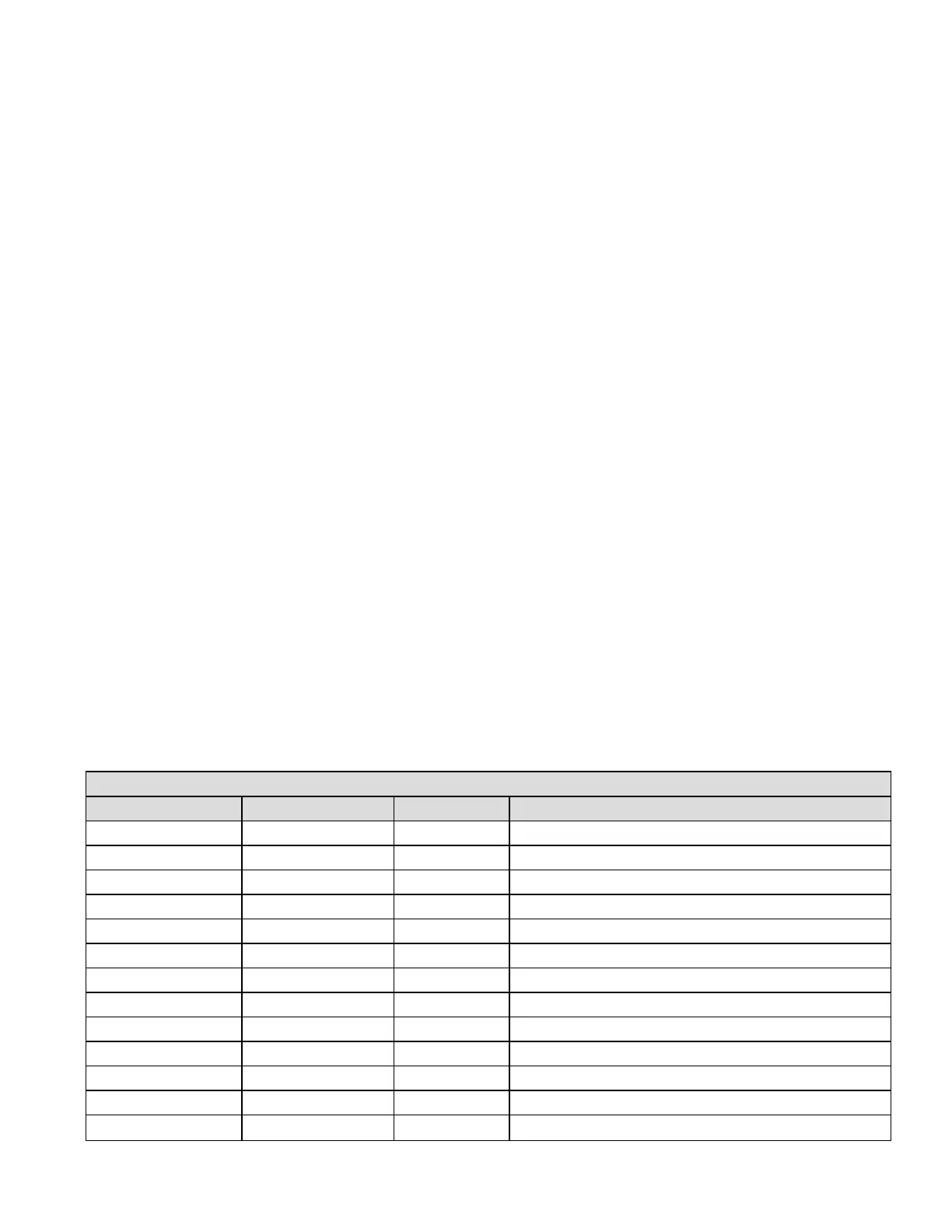
Table 1. Modbus Holding Registers
First MBReg Last MB Reg Datatype Description
40003 40004 float32 Alarm Level (0,1, or 2)
40005 40005 uint16 The most important active fault
40007 40007 uint8 Monitoring State (See Table 2)
40008 40008 int16 Heartbeat counter
40015 40015 int16 Temperature 1 (ºC *10)
40016 40016 int16 Temperature 2 (ºC *10)
40017 40017 int16 Temperature 3 (ºC *10)
40037 40038 float32 Output Current (mA)
40039 40039 int16 External 24 VDC supply (mV)
40040 40040 int16 Internal 3.3 VDC supply 1 (mV)
40042 40042 int16 Internal 3.3 VDC supply 2 (mV)
40043 40043 int16 Internal 30 VDC supply (mV)
40044 40044 int16 Internal 320 VDC supply (Volts)
Honeywell® FS24XPlus™ | User Manual
100

 Loading...


