CHAPTER
8
Appendix 5: HART® Developer Information
HART®
Note: The mA output shall have an external loop resistance between 250Ω and 600Ω with HART®.
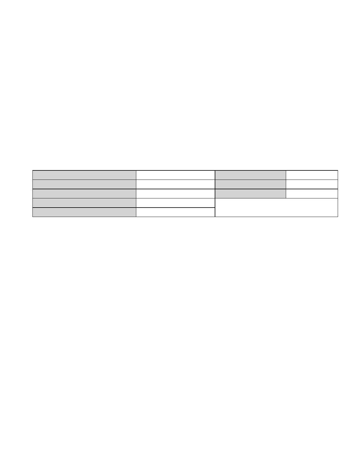
Device Identification
Manufacturer Name: Honeywell® Model Name(s): FS24XPlus™
Manufacture ID Code: 210 (D2 Hex) Device Type Code: 132 (84 Hex)
HART® Protocol Revision: 7.0 Device Revision: 1
Physical Layers Supported: FSK
Physical Device Category: Transmitter, Detector
The FS24XPlus™ will normally be mounted at height, typically secured to a wall with the with
bracket supplied Installation Kit (optional). The supplied Standard Adjustable Mounting Bracket
allows mounting on a plate, pole or other plant infrastructure. All bolts are captive to avoid
accidental loss during installation. The name plate is located opposite the field terminals and
indicates the model name and revision.
Universal Commands
Command #3 returns PV, units, and Loop Current. The first (PV) and the last (Loop Current)
variables are same.
Command #14 contains serial number of the device (3 bytes), followed by measurement units (1
byte) and 3 floating point variables for max, min, and span loop current in mA.
Honeywell® FS24XPlus™ | User Manual
60

 Loading...


