Honeywell® FS24XPlus™ | User Manual
38
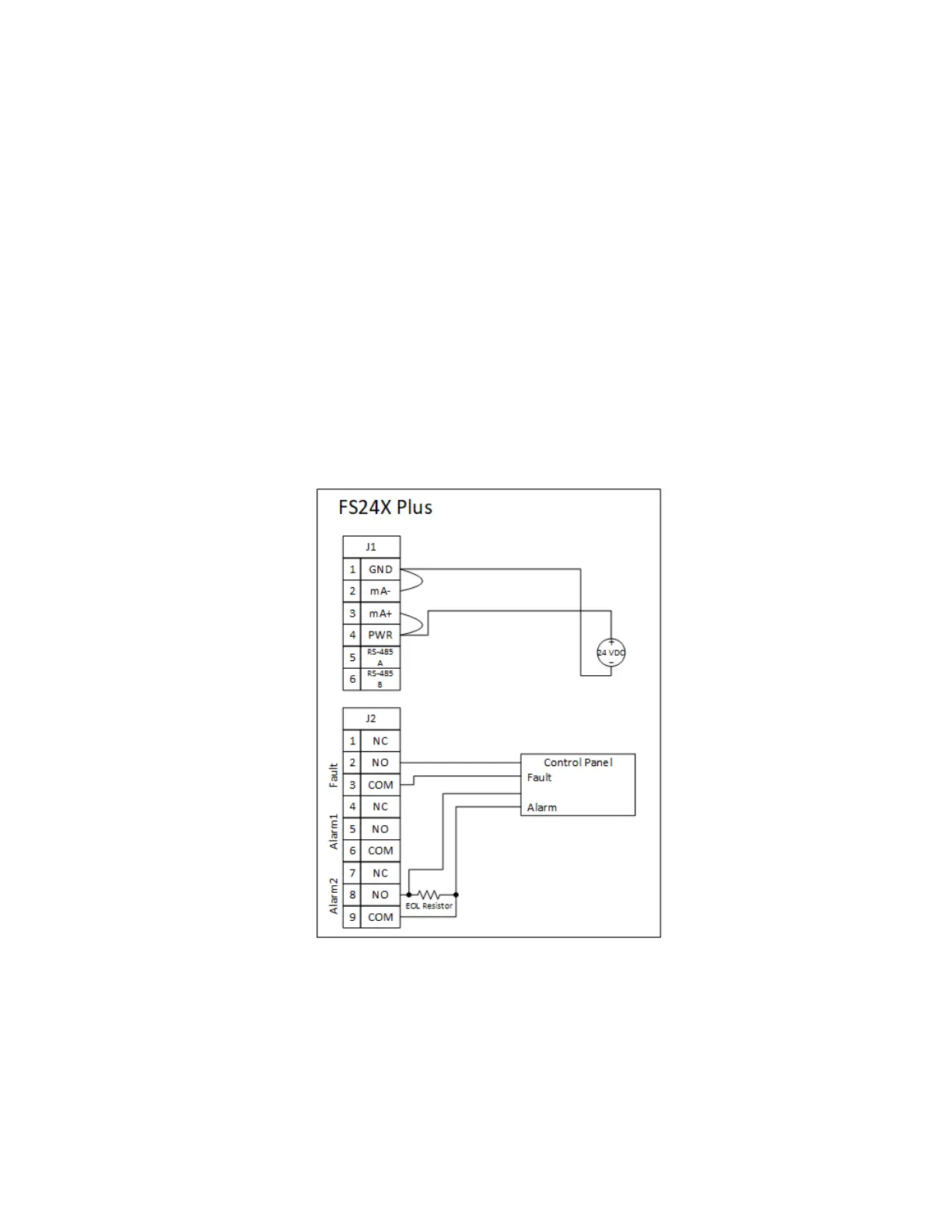
Communication Wiring
Independent Alarm and Fault Relay Interface Circuits
l Fault relay configured normally energized and wired using ordinarily open contact. i.e.,
continuity of the fault circuit will break if relay de-energized.
l Any loss of continuity in the power circuit will result in fault relay being de-energized and
fault condition being signaled to the controller.
l Alarm relay typically configured de-energized and wired using the normally open circuit. i.e.,
the alarm circuit is shorted in the event of an alarm.
l The EOL resistor (selected following control panel specification) enables the signal circuit to
be monitored by the control panel for continuity.
l Any loss of continuity in the alarm circuit, including the disconnect of either the signal
conductor, or the EOL resistor, or both will be detected by the controller and signal as a fault.
l The termination of the alarm circuit conductor and the EOL resistor (or the next unit in a
daisy chain of units) must be inserted into separate openings on the duplicate terminal block
of the NFPA 72 Connection Kit to comply with NFPA 72 requirements.

 Loading...


