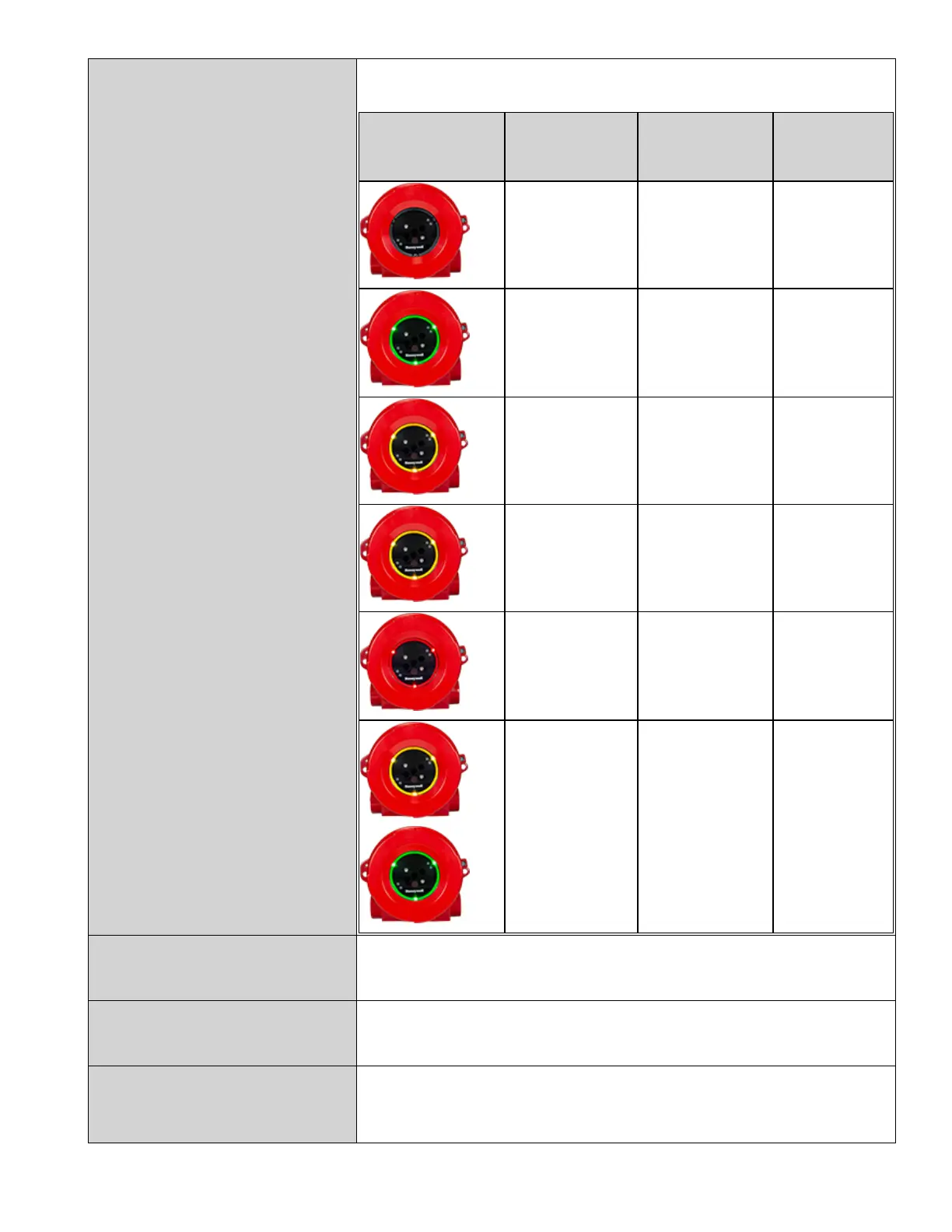
HALO flash patterns during operation:
Illustration State Default Pattern
Optional
(settable)
Pattern
Off or de-
energized
Off Same
Normal
Operation, No
fire
Mostly off,
flashing Green
every 5 seconds
Off
Inhibited Solid Yellow Same
Fault
Flashing Yellow
every second
Same
Alarm Solid Red Flashing Red
Warning
Flashing Yellow
and Green
Alternate
Same
Mean Time Before Failure:
>10 year MTBF with a commonly used database (e.g. MIL-217,
MIL-217D, or Siemens SN29500). Two calculations - All
components and only safety critical components.
Mounting Bracket:
Compatible with SM4 which has 10 degree increments of
adjustment in horizontal and vertical directions. SM4-M – marine
version available.
Enclosure:
Diameter: 125 mm (4.92 in) x 115 mm (4.52 in) deep; Two M25 X
1.5P or two ¾ ’’ NPT conduit entries.
Window size diameter: 79 mm (3.11 in)
Honeywell®FS24XPlus™ | User Manual
13

 Loading...


