Load Center Application
A load center application (also commonly referred to as the room controller unit or “RCU”) is
designed to locate all of the devices capable of providing DC power, relay outputs, TRIAC dim-
mer output, 0-10V dimming, and dry contact inputs for HVAC, lighting, drape control, into a
load panel that is located near the breaker box where the mains voltage is fed into the gues-
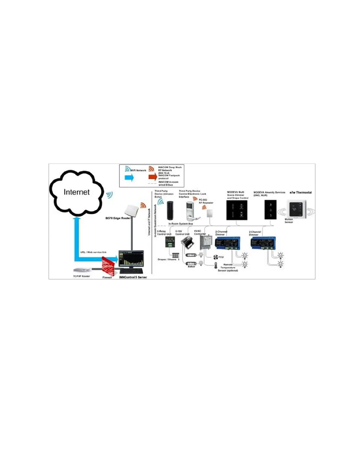
troom. In the below Load Center architecture diagram, the e7w Thermostat provides the user
interface to the guestroom controls but does not directly control the HVAC unit.
The e7w communicates via RF with PC502.4G room gateway which further communicates
with other in-room devices. The in-room devices like (MODEVA switch, X47 or X47 L.P, HVAC
controller etc.) communicates via S5 system bus with the PC502.4G.
For example, when a temperature UP button is pressed on the e7w thermostat, the thermostat
sends command via RF to PC502.4G. The PC502.4G further sends command to the HVAC
controller over S5 system bus, which actuates the FCU (Fan Coil Unit).
Figure 3: Load Center Application