Thor VM1 with Microsoft Windows Embedded Standard 2009 User Guide 239
Port and Connector Pinouts
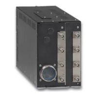
Power Supply Connector
VM1D Standard Dock and VM3D Enhanced Dock
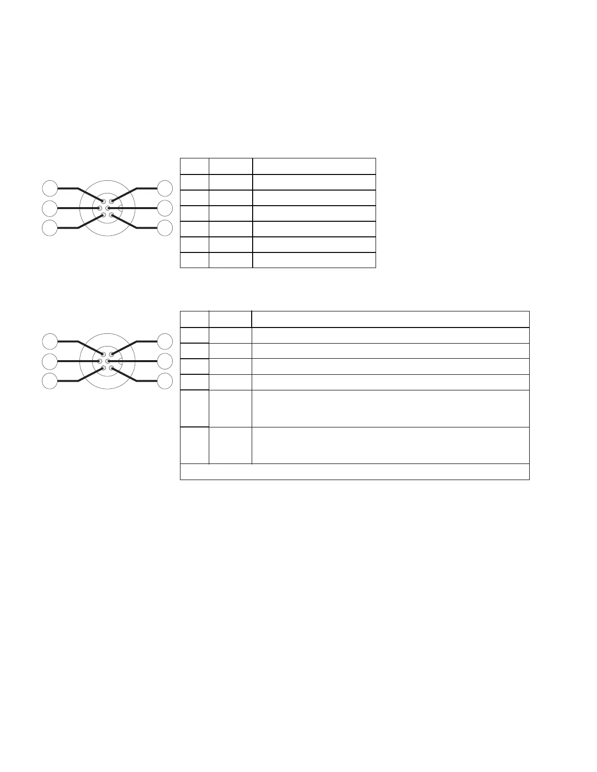
VMXD Enhanced Dock
Pin Signal Description
1V In+ 10-60V DC input +
2V In+ 10-60V DC input +
3V In- input -
4V In- input -
5 GND Chassis ground
6 Ignition +0V to 60V to start terminal
Pin Signal Description
1 V In+ 13.2V DC Input + provided by DC/DC power supply
2 V In+ 13.2V DC Input + provided by DC/DC power supply
3V In- Input -
4V In- Input -
5COM1
RTS
Screen Blanking Box + The green wire in the power cable must be
connected to the switched side of the screen blanking box. See
the applicable wiring diagram below.
6COM1
CTS
Screen Blanking Box - The white wire in the power cable must be
connected to the unswitched side of the screen blanking box. See
applicable wiring diagram below.
Cable shell provides chassis ground connection.

 Loading...