Thor VM1 with Microsoft Windows Embedded Standard 2009 User Guide 241
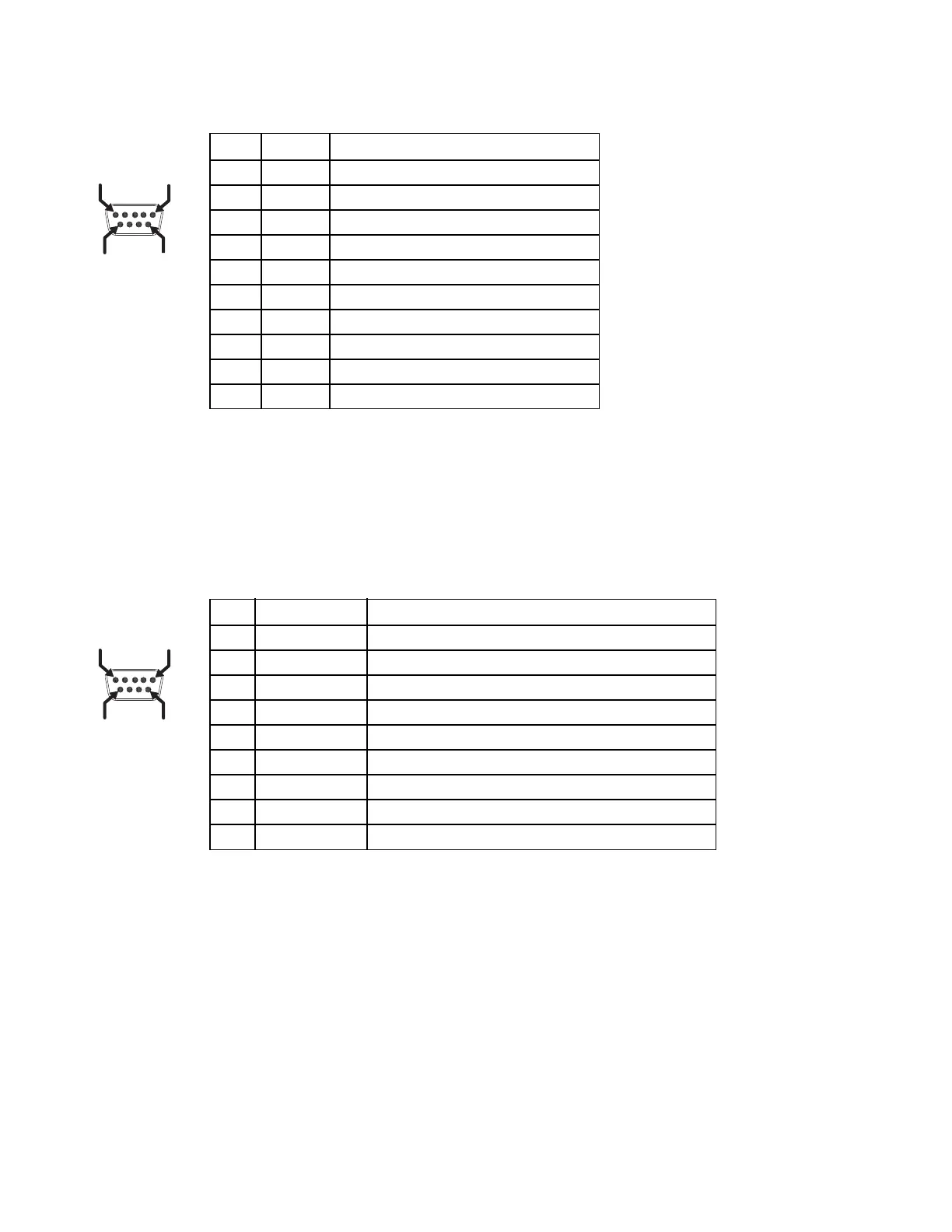
COM1 and COM2 Connector
VMXD Enhanced Dock only: Because the power supply connector port for the VMXD Enhanced Dock con-
tains COM1 RTS and CTS signals, the COM1 port on the dock should not be used when the power cable is
used for screen blanking to avoid port conflicts.
USB and USB1 Connector
The Standard Dock has a USB connector. The Enhanced Dock has a USB1 connector.
Pin Signal Description
1 DCD Data Carrier Detect – Input
2RXDReceive Data – Input
3 TXD Transmit Data – Output
4 DTR Data Terminal Ready – Output
5 GND Signal/Power Ground
6 DSR Data Set Ready – Input
7 RTS Request to Send – Output
8 CTS Clear to Send – Input
9 +5VDC Bar Code Scanner Power - 500mA max
Shell CGND Chassis Ground
Pin Signal Description
1 GND Common ground
2 USBC_D+ USB client data signal (not used)
3 USBC_D- USB client data signal (not used)
4 USB_H1_PWR USB host 1; 5V output power
5 GND Common ground
6 GND Common ground
7 USB_H1_D+ USB host 1 data signal
8 USB_H1_D- USB host 1 data signal
9 USBC_VBUS USB client 5V detect from attached host (not used)
PIN 6PIN 9
PIN 1
PIN 5
 Loading...