MAN0878-09-EN_XLE_XLT_UserManual
A u g u s t 2 3 , 2 0 1 8 P a g e 124 | 158
15.8 Digital / PWM Output Configuration
The following figure illustrates the Digital / PWM Output Configuration dialog. To open the I/O
configuration dialogs, select Controller → Hardware Configuration → Local I/O → Config (top
button) → Module Setup.
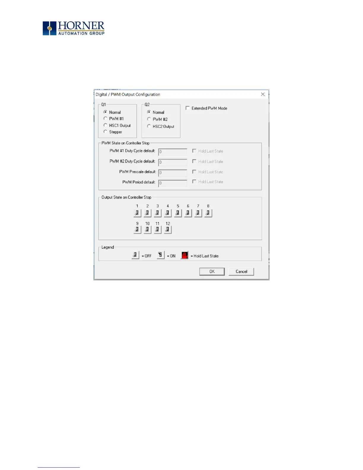
Figure 15.9 – Digital / PWM Output Configuration Dialog
The Q1 and Q2 group boxes allow the user to specify the operation of the multi-function outputs.
The PWM State On Controller Stop group box contains items that allow the user to specify how
the PWM outputs behave when the controller is stopped. These items can either hold their value
or default to some value when the controller is stopped.
NOTE: The PWM outputs are set to the OFF state at power-up and during program download
and remain in that state until the unit is placed in RUN.
The Output State On Controller Stop group box contains items to allow the user to specify how
the remaining digital outputs behave when the controller is stopped. These items can either
hold their value or default to some value when the controller is stopped.

 Loading...

