MAN0878-09-EN_XLE_XLT_UserManual
A u g u s t 2 3 , 2 0 1 8 P a g e 125 | 158
15.9 Analog Input Configuration
The following figure illustrates the Analog Input Configuration dialog. To open the I/O
configuration dialogs, select Controller → Hardware Configuration → Local I/O → Config (top
button) → Module Setup.
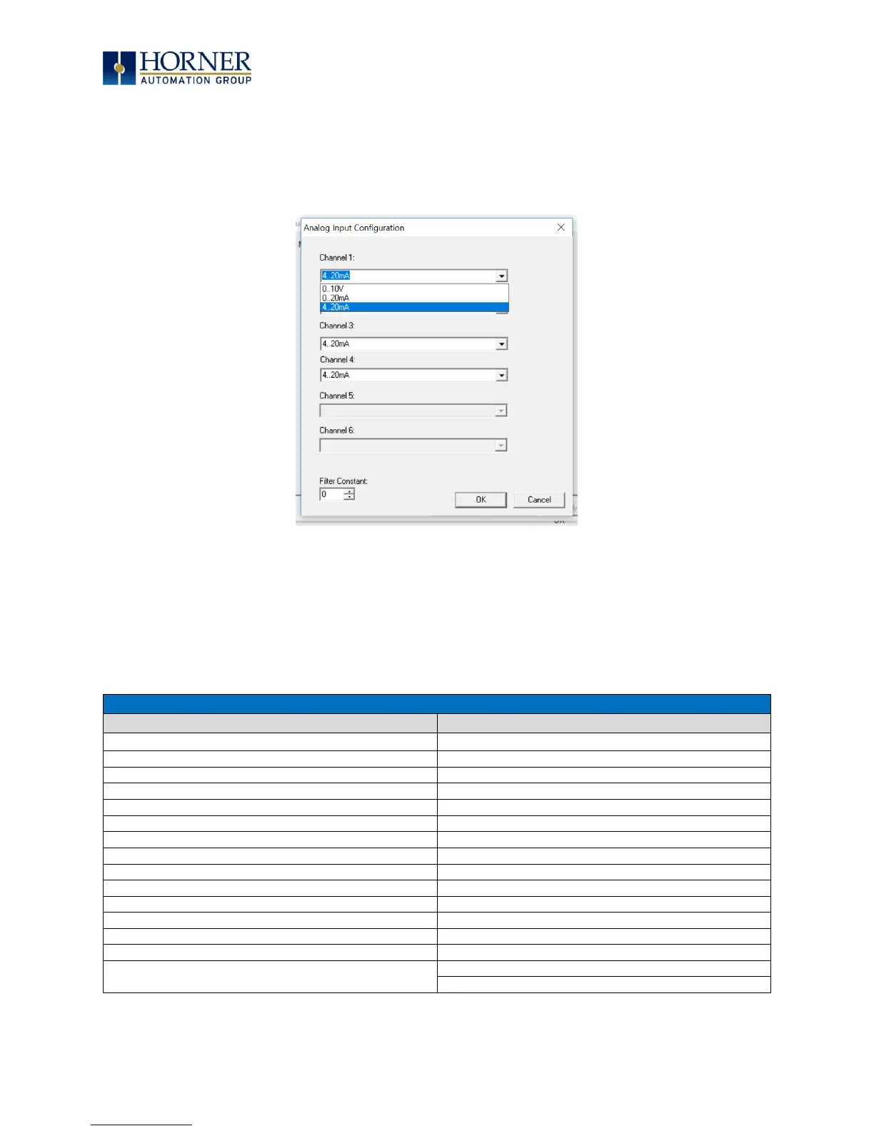
Figure 15.10 – Analog Input Configuration Dialog
The Channel x drop down windows allow the user to specify the mode for each analog input to
operate. The Channel x drop down windows are enabled/disabled according to which model is
being configured. All the models have the following modes available: 0..10V, 0..20mA, and
4..20mA.
On Model 5 and Model 6 I/O, other options on channels are outlined below:
Table 15.2. – Analog In for Models 5 & 6
Type J Thermocouple, 1/20°C
Type K Thermocouple, 1/20°C
Type N Thermocouple, 1/20°C
Type J Thermocouple, 1/20°C
Type T Thermocouple, 1/20°C
Type K Thermocouple, 1/20°C
Type E Thermocouple, 1/20°C
Type N Thermocouple, 1/20°C
Type R Thermocouple, 1/20°C
Type T Thermocouple, 1/20°C
Type S Thermocouple, 1/20°C
Type E Thermocouple, 1/20°C
Type B Thermocouple, 1/20°C
Type R Thermocouple, 1/20°C
* The Filter Constant provides filtering to all channels
on Model 5 .
Type S Thermocouple, 1/20°C
Type B Thermocouple, 1/20°C

 Loading...

